66550033-EN - V6.1 - 15/08/20
- 25 -
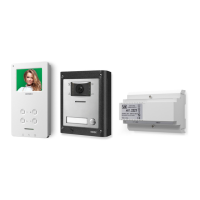
ESVK/6388 Series “2 wire Bus” videokit
ESVK/6388 Series - Installation handbook
Art.6388 3.5" hands free colour display digital videophone
PRIVACY DURATION
• Keep pressed the
button until the two LEDs and are switched on.
• Press the button for the number of times corresponding to the required privacy duration to set. Each time the button is
pressed, the duration is increased by 15 minutes: i.e. to set 2 hours, press the button 8 times.
Default: innite. Max value: 20 hours. To program innite privacy time don’t press any buttons.
• Once the required privacy time is reached, wait approx 5 seconds for the two LED’s to switch o. The new duration is set.
VIDEOPHONE ADDRESS SW1.1..7
The table below shows how to set the address of the videophone. Considering that ON = 1 and OFF = 0, multiply
each digit for the relevant decimal weight then sum values obtained to get the address: E.g. as highlighted in
the table OFF, ON, OFF, OFF, ON, OFF, ON in binary is equal to 0100101 then multiplying each digit for the rele-
vant decimal weight you obtain the address that is 37.
SWITCHES STATUS BINARY CODE DECIMAL WEIGHT ADDRESS
7 6 5 4 3 2 1 64 32 16 8 4 2 1
OFF OFF OFF OFF OFF OFF ON 0 0 0 0 0 0 1 1
OFF OFF OFF OFF OFF ON OFF 0 0 0 0 0 1 0 2
OFF OFF OFF OFF OFF ON ON 0 0 0 0 0 1 1 3
OFF OFF OFF OFF ON OFF OFF 0 0 0 0 1 0 0 4
OFF ON OFF OFF ON OFF ON 0 1 0 0 1 0 1 37
ON ON ON ON ON ON ON 1 1 1 1 1 1 1 127
Note: The maximum number of units allowed is 100 but the address of each unit can be a value between 1 and 127.
VIDEOPHONE END OF LINE TERMIANTION S3
Looking at the videophone from the rear:
Move the switch S3 to the lower position
to disable the bus termination.
Move the switch S31 to the upper posi-
tion to enable the bus termination.
In case of more units (intercoms, videophones or video monitors) in a parallel connection (bus wires are connected to the terminals
of the rst unit then from this to the second and so on up to 4 units max) the BUS termination must be enabled only for the last unit
in the chain while on all other units it must be set to disabled.
INTERCOMMUNICATION MODE SW2.1
This switch establishes the intercommunication mode: in OFF position (default) intercommunication is between units in
the same apartment (same addresses but dierent extension); in ON position the intercommunication is between units
in dierent apartments (dierent addresses).
On installations where there are more than one intercom/videophone in the same apartment and intercommuni-
cation between dierent apartments is required, only one intercom/videophone may be set with this function (SW2.1=ON,
SW2.2=OFF, SW2.3=OFF). The other intercom/videophones in the apartment must be set for local intercommunication with
extension addresses “2-4” (slaves). From the intercom/videophone set for intercommunication with other apartments it
will not be possible to intercommunicate within the apartment but slave extensions 2-4 will be able to intercommunicate
with each other within the apartment.
EXTENSION NO SW2.2..3
If the intercommunication between apartments is enabled (switch 1 of
SW2
= ON)
leave these two switches in default position (both to OFF). Otherwise, if the in-
tercommunication is between the same apartment (switch 1 of
SW2
= OFF), set
the extension addresses starting always from 1. During the external call, all video
monitors in the same at will ring but the video will be shown only from the vide-
ophone with extension address 1.
ON
1 2 3 4 5 6 7 8
SW1.1..7
ON
1 2 3 4
SW2.1
ON
1 2 3 4
SW2.2..3
2 3 EXTENSION NO.
OFF OFF 1 (default, master)
ON OFF 2 (slave)
OFF ON 3 (slave)
ON ON 4 (slave)