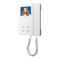
JUMPER SETTINGS
There are 3 internal jumpers (JP1-JP3). The rst 2 jumpers are for service push button functions the third sets the videophone as
either a master or a slave (this function is often used for videophones with parallel connections). Table 1 on page 2 shows the
default conguration for these jumpers and the available congurations.
TERMINALS AND RELEVANT SIGNALS
Table 2 on page 2 shows the functions available on the terminals. The table also shows (for compatibility with older systems)
the terminal markings used on the 900 series and 3000Series.
Table 1 - Jumper settings for Art.6231
Jumper
Jumper
position
Pin connector Button Push button function
B A
JP1
JP2
JP3
JP1
A
1T
Linked to pin connector “T”.
B Camera recall.
JP2
A
2T
Linked to pin connector “T”.
B Camera recall.
JP3
A Monitor switched o during call tone.
B Monitor switched on during call tone.
Table 2 - Art.6231 videophone signals
Art.6231 Art.3X31 Signal description
2T 13
See Table 1 on page 2 - push button
C 3
Camera recall button - push button
1 4
Call tone input.
Input/Output speech line.
Door opening – push button
5 Negative power input 0 Volt.
+ 6 Positive power input +15 - 20Vdc 0.45A.
V2 7 Video input +sync.
V1 8 Video input –sync.
CP 9 Local call tone input (at bell etc.).
T 11
Push buttons
, common terminal.
1T 12 See Table 1 on page 2 - push button
DL Door open LED +12Vdc input
12VI 12Vdc power input for LED privacy
TECHICAL SPECIFICATION
Voltages: 20Vdc (+2-5V)
Power consuption: Stand-by: 0mA
Operating: 100mA max
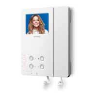
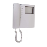
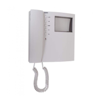
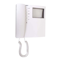
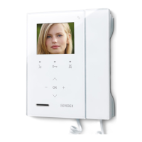
Art.6231 3.5" colour display videophone