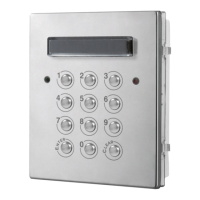
Art.8800 - Art.8800-3 Digital codelock module
REPROGRMMING GUIDE
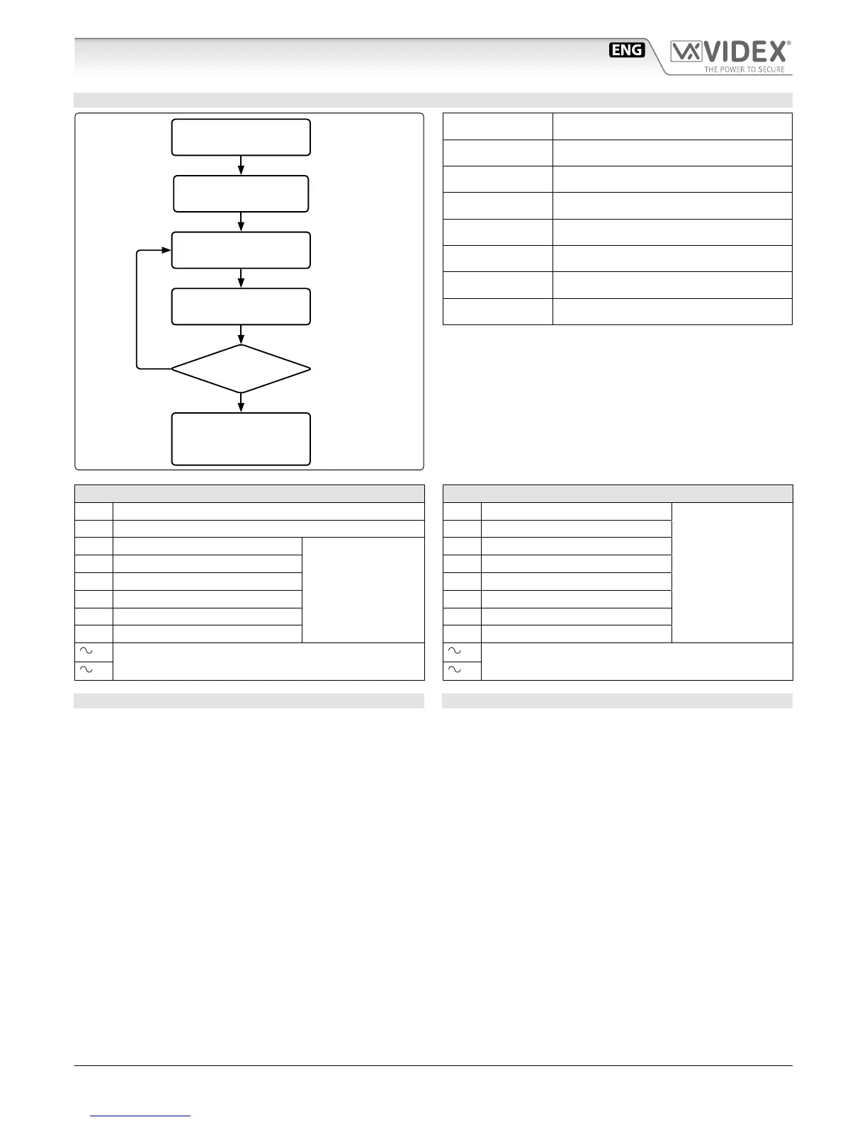
ENTER THE
ENGINEER’S CODE
REENTER THE
ENGINEER’S CODE
ENTER
ACCESS CODE
ENTER
ACCESS TIME
PRESS ENTER
TWICE TO EXIT
PROGRAMMING
MORE
DOORS?
Alternatively enter a
new engineer’s code
(4 to 8 digits)
Press Enter
(Red light will illu-
minate*)
Press Enter
Press Enter
Press Enter
Repeat steps for relay 2
and relay 3
***
YES
NO
Relay code (4-8 dig-
its) operate the door
or gate.**
Two digits (01-99
sec or 00 for remain
open)
Engineer’s code
Relay 1 code
Relay 2 code
Relay 3 code***
Relay 1 time
Relay 2 time
Relay 3 time***
Notes:
* If the red light does not illuminate, the engineer’s code is
incorrect. Follow instructions to return system to preset en-
gineer’s factory code.
** On the rst loop of the ow chart its relay 1, second loop is
relay 2 and third loop is relay 3.
*** Only for Art.8800-3
ART.8800 CONNECTION TERMINALS SIGNALS
SW1 Relay 1 command signal (active low)
SW2 Relay 2 command signal (active low)
NC2 Relay 2 normally closed contact
Max
24Vac/dc
5A
NO2 Relay 2 normally open contact
C2 Relay 2 common contact
NC1 Relay 1 normally closed contact
NO1 Relay 1 normally open contact
C1 Relay 1 common contact
/
+
12/24Vac/dc power input
/
–
ART.88003 CONNECTION TERMINALS SIGNALS
NO3 Relay 3 normally open contact
Max
24Vac/dc
5A
C3 Relay 3 common contact
NC2 Relay 2 normally closed contact
NO2 Relay 2 normally open contact
C2 Relay 2 common contact
NC1 Relay 1 normally closed contact
NO1 Relay 1 normally open contact
C1 Relay 1 common contact
/
+
12/24Vac/dc power input
/
–
TECHNICAL SPECIFICATIONS
Power requirements: 12/24V AC/DC, 2VA
Power Consumption: On AC On DC
Stand-by: 82mA 21.5mA
Operating: 125mA 35.0mA
Working Temperature: -10 +50° C
CLEANING OF THE PLATE
Use a clean and soft cloth. Use moderate warm water or non-ag-
gressive cleansers.
Do not use:
• abrasive liquids;
• chlorine-based liquids;
• metal cleaning products.