66250900 - V4.1 - 15/05/19
- 5 -
Kristallo Series
Art.KRV76-KRV78 - Installation instructions
VIDEO MODE SW2
The video mode setup is carried out by the 4 way Dip-Switch
accessible from the rear side of the videophone.
Switches 3 and 4 adjust the video signal impedance. when
using more than one videomonitor in parallel (without a
video splitter) put both switches in the OFF position on all
but the last videomonitor (end of line).
VIDEO MODE
Switches 1,2 Mode
ON
1 32 4
Coax
ON
1 32 4
Balanced
75 OHM VIDEO TERMINATION
Switches 3,4 Termination
ON
1 32 4
Enabled
ON
1 32 4
Disabled
VIDEOMONITOR ADDRESS SETUP SW1
Each videomonitor must be address is binary (PHONE ID) using the 8 way dip switches located on the rear of the unit. Each switch
correspond to one bit which can have a value 0 (OFF) or 1 (ON). Each bit corresponds to a decimal weight depending on the posi-
tion: Switch 1 = decimal 1, 2=2, 3=4, 4=8, 5=16, 6=32, 7=64, 8=128. I.E. to set the address 37, put switches 1, 3 and 6 on (1+4+32=37).
SWITCHES DECIMAL WEIGHT ADDRESS
8 7 6 5 4 3 2 1 128 64 32 16 8 4 2 1
OFF OFF OFF OFF OFF OFF OFF ON 0 0 0 0 0 0 0 1 1
OFF OFF OFF OFF OFF OFF ON OFF 0 0 0 0 0 0 1 0 2
OFF OFF OFF OFF OFF OFF ON ON 0 0 0 0 0 0 1 1 3
OFF OFF OFF OFF OFF ON OFF OFF 0 0 0 0 0 1 0 0 4
OFF OFF ON OFF OFF ON OFF ON 0 0 1 0 0 1 0 1 37
ON OFF ON ON OFF ON OFF OFF 1 0 1 1 0 1 0 0 180
CONNECTION TERMINALS SIGNALS
DOL 12Vdc input to supply “door open” LED
SB
Open collector output (active low) for service call but-
ton. When the monitor is switched on, keep pressed
the button until the service is enabled. Once enabled
the output remains active for 2s approx
AL
Active low input for alarm signal. When active, the
system sends the alarm to the concierge if installed
and enables the Art.512DR if installed and properly
congured for the alarm management
LB Active low input for local call “Local Bell”
L BUS DATA line input
— BUS Ground line input
12Vin Stand-by +12Vdc power supply input
12Vout +12Vdc stabilized output
GND Power supply ground input / coax video ground
V2/V
Balanced video signal V2 sync.(balanced video signal
mode) Composite video signal (coax video signal mode)
V1 Balanced video signal V1 sync
+20 +20Vdc power supply input
+VD
+12Vdc power supply output for video distributor
Art.894/Art.894N
NOTE
When connecting the 12Vin & 12VOut an addition Art.893N1
PSU is required for every 50 devices.
TECHNICAL SPECIFICATION
Working voltage: 17÷20Vdc
12÷14Vdc
Power consumption: 6mA in stand-by (on 12Vdc)
200mA Max (on 12Vdc)
250mA Max (on 20Vdc)
Working temperature: -10°C +50°C
MEMORY BOARD
This device is also available in
the version with memory board
(Art.KRV76/VM and Art.KRV78/VM).
If you have that version, please refer to the
“Kristallo Series 3.5" Memory Board” user
manual (in English and Italian) for installation
and use.
The manual is available for download: click/tap or scan the
QR code.
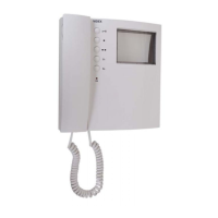
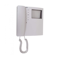
Art.KRV76-KRV78
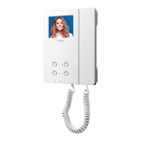
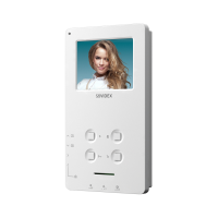
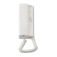
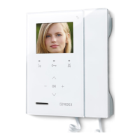
Handsfree videophones for systems using composite video signal (coax) or balanced (two wires)
 Loading...