6
6. Anschluss
Alle Anschluss- und Montagearbeiten dürfen
nur bei abgeschalteter Betriebsspannung
durchgeführt werden!
Verwenden Sie nur nach VDE /EN-gefertigte
Modellbahntransformatoren!
Sichern Sie die Stromquellen unbedingt so
ab,dassesbeieinemKurzschlussnicht
zumKabelbrandkommenkann.
Die Betriebsspannung beträgt 16 V ~.
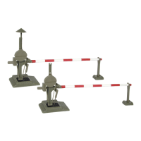
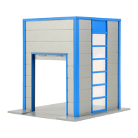
Schließen Sie die Schranken gemäß Abb. 5 oder
6an.ZurBedeutungderKabelfarbensieheAbb.
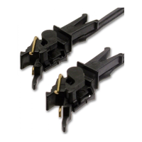
3. Für den zuggesteuerten Betrieb benötigen Sie
Schaltgleiseoder-Kontakte(z.B.6840&6841).
Bei zweigleisigem Betrieb ist ein elektronisches
Relais5552erforderlich.Dadurchwirderreicht,
dass bei gleichzeitigem Überqueren des Bahnü-
berganges von zwei entgegenkommenden Zügen
die Schranken erst wieder geöffnet werden, wenn
beide Züge den Bahnübergang verlassen haben.
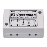
Die Antriebe der H0-Bahnschranke (5100) verfü-
gen über jeweils einen zusätzlichen Schaltkontakt.
Dieser können Sie nutzen, um z. B. eine Blinke-
lektronik für Andreaskreuze (z. B. 5835) zu steu-
ern. Hierzu führen Sie eine der beiden Stromver-
sorgungsleitungen der Blinkelektronik über den
KontakteinesderbeidenAntriebe.
Gleichstrombetrieb: Schließen Sie die gelben
KabelandenMinuspoldesTrafosan.
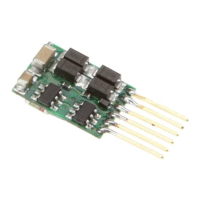
7. Digitale Ansteuerung
Die Viessmann Bahnschranken lassen sich ohne
Probleme auch mit einem Digitalsystem ansteu-
ern. Schließen Sie die Antriebe der Bahnschran-
ken dazu an einen Magnetartikeldecoder z. B.
den 5211 (Märklin-Motorola) oder 5212 (DCC) wie
eine Weiche oder ein Signal an. Achten Sie da-
rauf,nebendenblauenauchdasgelbeKabelfür
die Stromversorgung anzuschließen.
Hinweis für digitales Schalten
Der Viessmann Universalantrieb benötigt für
den ordnungsgemäßen Betrieb eine Schalt-
spannung von mindestens 16 Volt.
Verwenden Sie ausschließlich Magnetarti-
keldecoder mit separater Schaltspannungs-
einspeisung (z. B. alle Viessmann Magnetar-
tikeldecoder) und einen ausreichend starken
Trafo (z. B. Viessmann 5200 oder 5201,
vorzugsweise in Verbindung mit dem Viess-
mann Powermodul 5215).
6. Connections
Make sure that the power supply is switched
off when you mount the device and connect
the wires!
Only use VDE/EN tested special model train
transformers for the power supply!
The power sources must be protected to
prevent the risk of burning wires.
The operating voltage is 16 V AC.
Nowmaketheelectricalconnectionaspergure
5 or 6. For the meaning of the cable colours re-
fertogure3.Tocontrolthegatesbytrains,you
need switching tracks or -contacts (e. g. Viess-
mann track contact for H0 6840 & 6841)
An electronic relay 5552 is required for two-track
operation. This is necessary so that when two
trains approaching each other cross the railroad
crossing at the same time, the beams do not open
until both trains have left the crossing.
The drive units of the H0-railroad crossing gates
(5100) are including an additional switching con-
tact. This can be used to control the blinking elec-
tronics of warning lights (e. g. 5835). To use this
function, please connect one of the wires for the
electric current of the blinking electronic with the
contact of one of the drive units.
Direct current: Connect both yellow cables to the
negative pole of the transfomer.
7. Digital Control
The Viessmann railroad crossing gates can be
controlled without problems using a digital system.
For digital control of the gates, connect the drive
units to an accessory decoder such as the 5211
(Märklin-Motorola) or 5212 (DDC) in the same
way as a turnout or a signal. Remind, that you
have to connect not only the blue cables but also
the yellow cables for power supply!
Important information
for digital switching
The Viessmann universal drive requires a
switching voltage of minimum 16 Volt for
proper operation.
Therefore you should use accessory decod-
ers with a separate switching voltage input
only (e. g. all Viessmann decoders).
For power supply, use a powerful transform-
er (e g. Viessmann 5200 or 5201) combined
with the Viessmann power module 5215.