11
close
schließen
größte Zuglänge größte Zuglänge
blau (grün Markierung) / blue (green marker)
blau (rote Markierung) / blue (red marker)
DIGITAL ZENTRALE
oder
16 V ~
oder
16 V = (braun ist positiv)
COMMAND STATION
or
16 V ~
or
16 V = (brown is positive)
braun / brown
gelb / yellow
Sekundär
0-10-16 V~
16 V
Primär
230 V~
Gefertigt nach
VDE 0570
EN 61558
Lichttransformator
5200
Nur für trockene Räume
Primär 230 V 50 - 60 Hz
Sekundär max. 3,25 A52 VA
ta 25°CIP 40
10 V
0 V
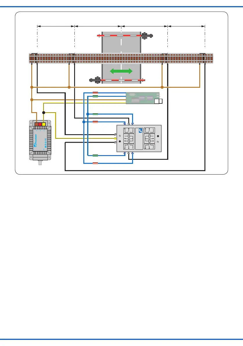
größte Zuglänge größte Zuglänge
Longest train Longest train Longest train Longest train
blau (rote Markierung) / blue (red marker)
Fahrtrichtung
schwarz / black
schwarz / black
schwarz / black
schwarz / black
gelb / yellow
schwarz / black
schwarz / black
gelb / yellow
braun / brown
blau (rote Markierung) / blue (red marker)
blau (grün Markierung) / blue (green marker)
blau (grün Markierung) / blue (green marker)
Schaltgleis / Switching TrackSchaltgleis / Switching Track
Elektr. Relais 5552
Viessmann
Fig. 10
Abb. 10
6. Connecting accessories
Sound module for a signal bell
The decoder of the barrier is suitable for connecting
a sound module for a signal bell. How to wire the
Viessmann sound module (item-No. 5556) is shown in
g.12.
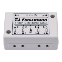
Blinking lights for the St. Andrew´s crosses
The decoder of the barrier does not have any other
terminals for additional accessories besides the sound
module. However, you may connect the blinking mod-
ule (item-No. 5065) for the warning lights of the St.
Andrew´s crosses in parallel to the sound module.
Please note that the green wire must be connected via
a 330 Ohm/0.25 Watt resistor to the blinking module.
In digital mode the warning lights can also be operated
with a digital switching decoder and a blinking module.
For more information please refer to chapter 7 (Digital
operation).
7. Digital operation
These barriers are suitable for analogue (analogue)
and digital operation.
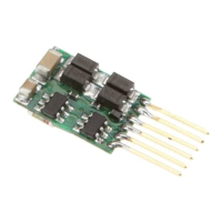
The integral decoder supports the DCC and the MM
(Märklin/Motorola) data formats and it can be controlled
by a suitable digital command station (e. g.: Commander
item-No. 5300).
6. Anschluss von Zubehör
Soundmodul für Läutewerk
Der Schrankendecoder ist bereits für den Anschluss
eines Soundmoduls für das Läutewerk vorbereitet.
Der Anschluss des Viessmann Soundmoduls Bahnüber-
gang (Art.Nr. 5556) ist in Abb. 12 dargestellt.
Blinklicht für beleuchtete Andreaskreuze
Der Schrankendecoder hat keine Anschlüsse für weiteres
Zubehör. Allerdings kann das Blinkmodul (Art.-Nr. 5065)
für die Andreaskreuze parallel zum Soundmodul ange-
schlossen werden.
Bitte beachten Sie, dass das grüne Kabel über einen
Widerstand mit 330 Ohm mit einer Leistung von 0,25
Watt angeschlossen werden muss.
Die Warnlichter der Andreaskreuze können im Digital-
betrieb auch über einen Schaltdecoder und eine Blink-
lichtelektronik gesteuert werden.
Näheres nden Sie im Kapitel 7 (Digitalbetrieb).
7. Digitalbetrieb
Diese Bahnschranke ist für analogen und digitalen Be-
trieb ausgelegt.
Der integrierte Digitaldecoder unterstützt die Formate
DCC und MM (Märklin/Motorola) und ermöglicht die Steu-
erung über eine geeignete Digitalzentrale (z. B.: Com-
mander Art.-Nr. 5300).