7
min. 1 train length
blau / blue
braun / brown
gelb / yellow
grüne Markierung
green marker
10-16V AC ~
14-24V DC =
13-24V Digitalsignal
zum Soundmodul und Andreaskreuz
To the soundmodule and St. Andrew‘s crosses
blau / blue
braun / brown
gelb / yellow
rote Markierung
red marker
Fahrtrichtung
öffnen
open
öffnen
open
schließen
close
schließen
close
mind. 1 Zuglänge
blau (grüne Markierung) / blue (green marker)
blau (rote Markierung) / blue (red marker)
gelb / yellow
braun / brown
zu den Schranken
To the barriers
min. 1 train length
mind. 1 Zuglänge
14-16 V ~/=
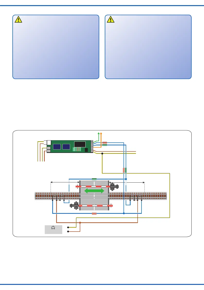
Fig. 6
Abb. 6
5. Anschluss
Vorsicht:
Alle Anschluss- und Montagearbeiten nur bei abge-
schalteter Betriebsspannung durchführen!
Ausschließlich nach VDE / EN-gefertigte
Modellbahntransformatoren verwenden!
Stromquellen unbedingt so absichern, dass es bei
einem Kurzschluss nicht zum Kabelbrand kommen
kann.
Widerstand und Diode an den Enden der
Anschlussdrähte sind für die Funktion erforderlich.
Keinesfalls entfernen! Widerstände nicht mit Isolati-
onsmaterial umhüllen, da sonst keine ausreichende
Kühlung möglich ist!
Schließen Sie die Schranken je nach Art des Betriebs-
systems und der Ansteuerung gemäß den Abbildungen
6 bis 13 an. Zur Bedeutung der Kabelfarben siehe Abb. 3.
Gleichstrombetrieb: Schließen Sie die gelben Kabel
an den Minuspol der Stromversorgung an. Diese Bahn-
schranke ist für analogen und digitalen Betrieb ausge-
legt. Der integrierte Digitaldecoder für die Formate DCC
und MM (Märklin/Motorola) ermöglicht auch die Steue-
rung über eine geeignete Digitalzentrale (siehe Kapitel 7).
5. Connection
Caution:
Make sure that the power supply is switched off when
you mount the device and connect the wires!
OnlyuseVDE/ENtestedspecialmodeltraintrans-
formers for the power supply!
The power sources must be protected to prevent the
risk of burning wires.
Resistor and diode at the cables are needed for prop-
er function of the lamp. Never cut them off! Never
cover resistor or diode with insulation material, be-
cause they have to be cooled by surrounding air!
Wire the barriers subject to the operating system used
accordingtog.6to13.Alsorefertog.3foranexpla-
nation of the colour coding of the wires.
DC operation: Connect the yellow wire to the “-“
(minus) terminal of the power supply unit.
These barriers are suitable for analogue (analogue) and
digital operation. The integral decoder supports DCC and
MM (Märklin/Motorola) and can be controlled by a suit-
able digital command station (refer to chapter 7 – digital
operation).
Ansteuerung der Schranken
Es gibt mehrere Möglichkeiten einen zuggesteuerten
Betrieb zu realisieren:
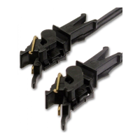
• Mit Schaltkontakten (Reed-Kontakte und Magnete
z. B.: Viessmann Art.-Nr. 6840 und 6841),
• mit Schaltgleisen,
• mit Gleisbesetztmeldern (analog oder digital;
z. B. Viessmann Art.-Nr. 5206).
Controlling the barriers
There are several possibilities for controlling these barri-
ers by the trains:
• With track contacts (Reed contacts and magnets
e. g.: Viessmann item-No. 6840 and 6841),
• with switching tracks (activated by each wheel resp.
axle),
• with occupancy detectors (analogue or digital; e. g.
Viessmann item-No. 5206).