3
Sekundär
0-10-16 V~
16 V
Primär
230 V~
Gefertigt nach
VDE 0570
EN 61558
Lichttransformator
5200
Nur für trockene Räume
Primär 230 V 50 - 60 Hz
Sekundär max. 3,25 A52 VA
ta 25°CIP 40
10 V
0 V
zum Gleis
gn
Vorsignal -
Steuerung
rt
viessmann
Steuermodul für
Licht-Blocksignal
5221
5
16 V
bn ge
rt / rd
rt / = rot /
gn / = grün /
rd red
gn green
gn / gnrt / rd
16 V~ AC
5221
schwarze Markierung
black marking
4011, Ω 4014,
4411, Ω 4414,
4811, 4911
grüne Markierung
green marking
Diode
diode
rote Markierung
red marking
gn / gn
braun / brown
gelb / yellow
gelber Stecker
yellow plug
brauner Stecker
brown plug
roter Stecker
red plug
grüner Stecker
green plug
z. B. / e. g. 5200
Fig. 1
Abb. 1
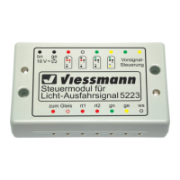
Das Steuermodul für Licht-Blocksignale Art.-Nr. 5221 wird
über Taster (z. B. Art.-Nr. 5545 oder 5547), Gleiskontakte
(z. B. Art.-Nr. 6840 für Baugröße H0) oder Schaltgleise
angesteuert.
Über die Buchse „Vorsignal-Steuerung“ kann ein Steuer-
modul (z. B. Art.-Nr. 5220) für das zugehörige Vorsignal
angesteuert werden.
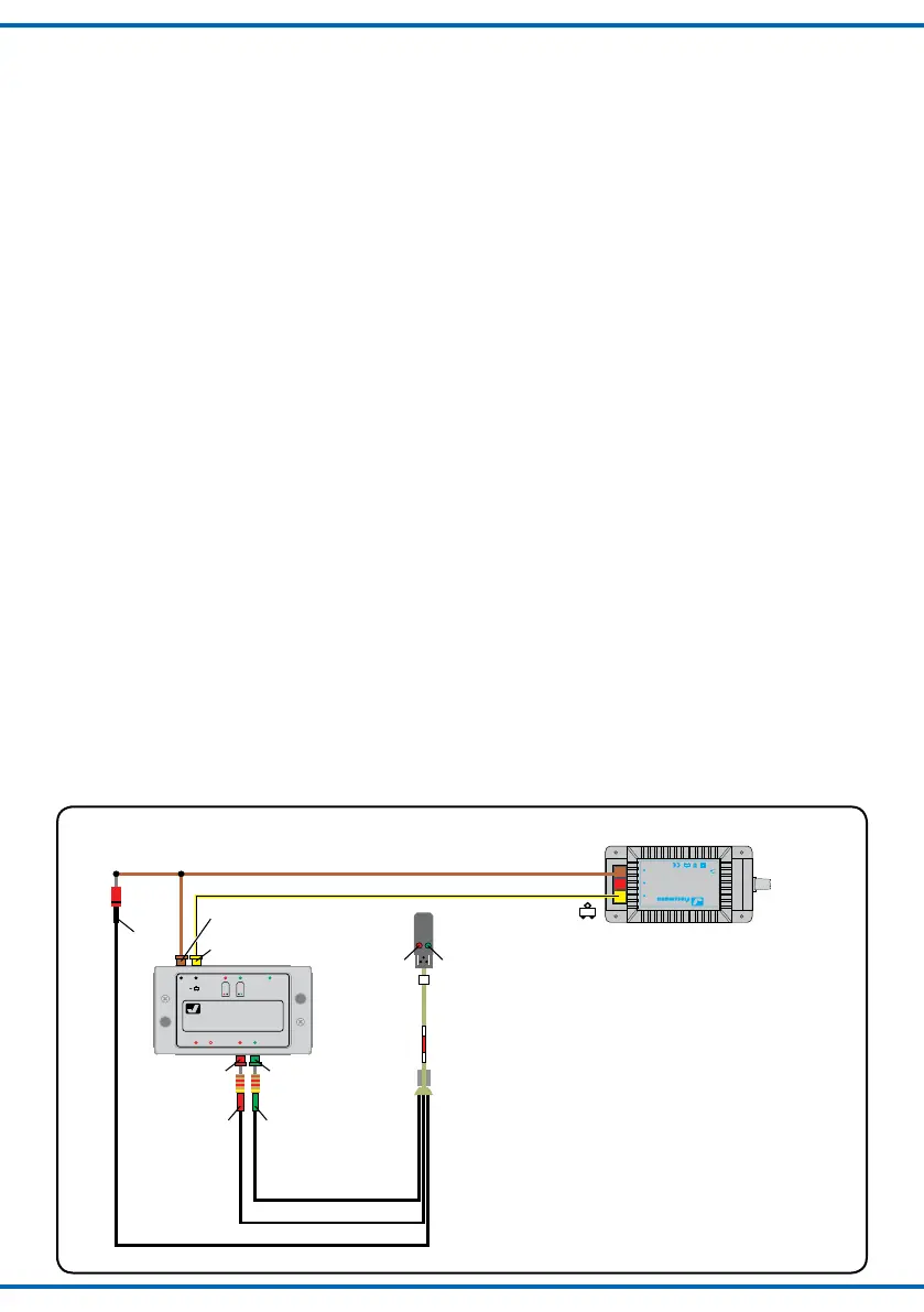
3. Anschluss
3.1 Anschluss von Versorgungsspannung
und Signal
Zur Spannungsversorgung ist das Modul über die oben
links liegenden Buchsen („bn“ und „ge“, d. h. braun und
gelb) an den 16 V-Wechselspannungsausgang eines Mo-
dellbahntransformators (z. B. Art.-Nr. 5200) anzuschlie-
ßen.
Das Lichtsignal wird an die unten am Steuermodul be-
findlichen, mit den Farben der entsprechenden Signal-
LEDs bezeichneten Buchsen angeschlossen.
Der gemeinsame Rückleiter des Lichtsignals (an dem
sich die Diode befindet) wird an die braune Buchse („bn“)
des Steuermoduls angeschlossen (= „Masse“).
The control module for colour light block signals item-No.
5221 can be operated with push button panels (e. g.
item-No. 5545 or 5547), track contacts (e. g. item-No.
6840 for H0 gauge) or switching tracks.
A control module item-No. 5220 can be controlled via
the socket “Vorsignal-Steuerung” for the corresponding
colour light distant signal.
3. Connection
3.1 Wiring of power supply and signal
The top left terminals (“bn” and “ge” – German for brown
and yellow) have to be wired to the 16 V-terminals (light-
ing output) of a model train transformer (e. g. item-No.
5200).
The colour light signal has to be connected with the
corresponding colour-coded sockets located at the
bottom of the control module. These sockets are colour-
coded with the corresponding colours of the signal LEDs.
The common pole of the colour light signal (where the
diode is located) has to be connected to the brown
socket (“bn”) of the control module resp. the transformer
(= “common ground”).