5
Fahrtrichtung
zum Gleis
gn
Vorsignal -
Steuerung
rt
viessmann
Steuermodul für
Licht-Blocksignal 5221
16 V
bn ge
gn1 gn2ge2ge1
Steuermodul für
viessmann
Licht-Vorsignal 5220
16 V
bn ge
400 m, 700 m oder/ 1.000 mor
4010, 4030,
4410, 4910 4011, 4411,
4811, 4911
52215220
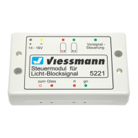
grüner Stecker
green plug
direction of travel
lila / purple
steuert dieses
Standard-
Licht-
Blocksignal
controls this
standard
colour light
block signal
bleibt frei
remains free
grüner Stecker
green plug
steuert dieses
Standard-
Licht-
Vorsignal
controls this
standard
colour light
distant signal
driving direction
Fig. 4
Abb. 4
Fahrtrichtung
zum Gleis
gn
Vorsignal -
Steuerung
rt
viessmann
Steuermodul für
Licht-Blocksignal 5221
5
16 V
bn ge
Fahrstrom
propulsion
current
entspricht dem Mittelleiter bei Märklin-Schienen
corresponds to the centre rail of Marklin tracks
rote Stecker
red plugs
braun / brown
rot / red
ca. 2 Loklängen
approx. 2 locomotive lengths
rot / red
Trennstelle
rail insulation
Trennstelle
rail insulation
driving direction
5221
16 V~ AC
gelber Stecker
yellow plug
brauner Stecker
brown plug
rot / red
rot / red
rot / red
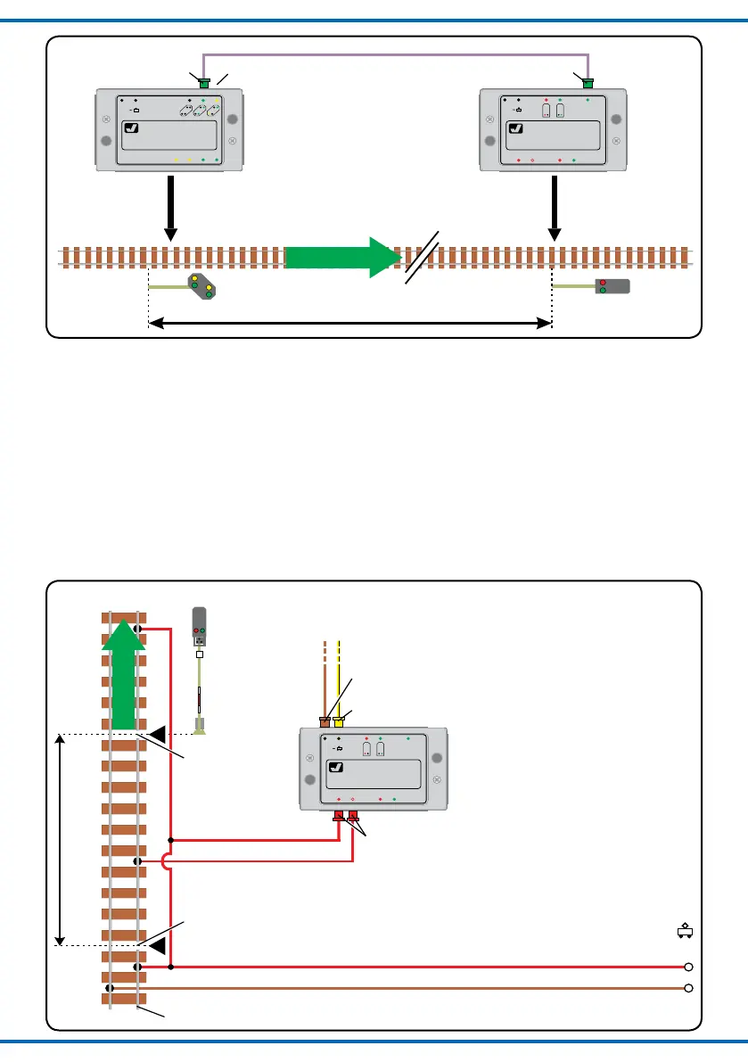
Abb. 5
Fig. 5
3.4 Zugbeeinussung
Die Signalsteuermodule sind mit einem Kontakt für die
Zugbeeinflussung ausgestattet. Bei „Halt“-zeigendem Si-
gnal (Hp0) kann damit der Strom am Gleis abgeschaltet
werden, sodass die Lokomotive vor dem Signal automa-
tisch anhält.
Hierzu ist in einem Bereich von ca. 2 Lokomotivlängen
vor dem Signal ein Schienenprofil bzw. bei Märklin-Glei-
sen der Mittelleiter mittels Isolierschienenverbindern Ihres
Gleissystemherstellers (bzw. Mittelleiterisolierungen)
elektrisch zu trennen (siehe Abb. 5). In der Regel wird
hierzu das in Fahrtrichtung rechts liegende Schienenpro-
fil gewählt.
3.4 Automatic train control
Viessmann signal control modules are equipped with
a contact for automatic train control. When the signal
shows the “stop” aspect (Hp0) the track in front of the
signal is disconnected and the locomotive stops auto-
matically.
To achieve this you have to electrically isolate a track
section (or the centre rail-contacts of the Märklin tracks)
of approx. 2 locomotive lengths in front of the signal by
means of insulating rail connectors matching your track
system (or insulate the centre rail-contacts). Usually the
right hand track (in direction of travel) is
insulated (see fig. 5).