12
U
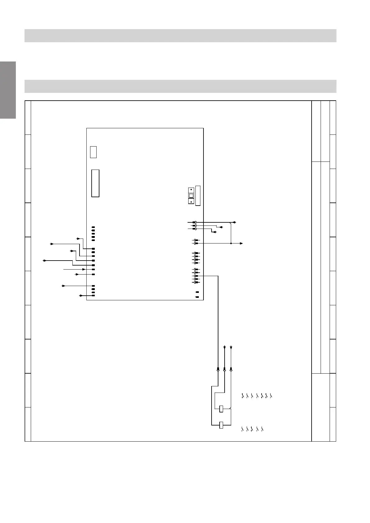
Primary pump
V
Secondary pump
W
Compressor relay (230 V~)
x
Enable compressor switching
Sheet 4: Main PCB
0 1
2 3 4
5 6 7
8 9
0 1
2 3 4
5 6 7
8 9
viesmann
Main PCB
Sheet 4
1
-216
2 3 4
1
-215
2 3 4 5 6 7 1
-214
2 3 4 5
-210
1
2
N
-40
PE
L
1
-213
1
-212
2 3 4
2
1
-211
2 3 4 5
-136
1
2
A1
A2
-K1
A1
A2
-K2
N
-L
/5.7
-L1´
5.6
-N
-PE
-N
2.3
2a.3
A
2.4
2a.4
2.3
2a.3
2.3
2a.3
2.7
2a.3
2.5
2a.5
1.5
1a.5
B
C
F
E
D
K
H
F3 2.0 A (slow)
X1
X2
M
L
14
13
/7.1
1413 /7.a.5
1413 /7.b.2
2423 /7.1
2423 /7.a.5
2423 /7.b.3
3433 /7.a.5
14
13
/7.1
1413 /7.a.3
1413 /7.b.2
2423
/7.a.3
3433 /7.a.4
2.2
2a.2
G
Fig. 6
A
External demand
B
External blocking
C
Power-OFF
D
Phase monitor (if installed) or jumper
E
Primary circuit pressure switch and/or frost stat
F
Safety high pressure switch
G
Primary circuit flow switch
H
Thermal relay
K
Ribbon cable to the controller and sensor PCB
Connection and wiring diagram
Sheet 3: EEV PCB (refrigerant circuit… (cont.)
6152053
Service





 To Next Page