Do you have a question about the Viessmann VITOCAL Series and is the answer not in the manual?
Detailed technical specifications for 230 V appliances, including heating and cooling performance data.
Detailed technical specifications for 230 V appliances, including heating and cooling performance data.
Details on refrigerant type, charge, global warming potential, and CO2 equivalent.
Graphical representation of application limits for heating and cooling based on EN 14511.
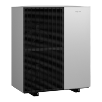
Detailed dimensional drawings and connection points for outdoor units.
Heating performance diagrams (output, consumption, COP) for specific outdoor unit types.
Heating performance diagrams (output, consumption, COP) for specific outdoor unit types.
Heating performance diagrams (output, consumption, COP) for specific outdoor unit types.
Heating performance diagrams (output, consumption) for specific outdoor unit types.
Heating performance diagrams (output, consumption) for specific outdoor unit types.
Heating performance diagrams (output, consumption) for specific outdoor unit types.
Heating performance diagrams (output, consumption) for specific outdoor unit types.
Heating performance diagrams (output, consumption) for specific outdoor unit types.
Heating performance diagrams (output, consumption) for specific outdoor unit types.
COP values for heating performance across different operating points and flow temperatures.
Cooling capacity, power consumption, and EER for specific outdoor unit types.
Guidelines for siting the outdoor unit, considering atmosphere, wind, and accessibility.
Criteria for selecting the installation location, focusing on air circulation, wind, and noise.
Minimum clearances required for outdoor units of types 201.A04-A08 and 221.A04-A08.
Minimum clearances for heat pump cascades, with different layout options.
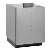
Diagram and details for floorstanding installation with support and line entry above ground.
Diagram and details for floorstanding installation with support and line entry below ground.
Diagram and details for wall mounting the indoor unit, including bracket and cable routing.
Requirements for the installation room, including temperature and humidity.
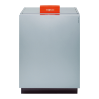
Diagrams showing minimum clearances required around the Vitocal 200-A indoor unit.
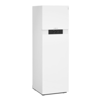
Diagrams showing minimum clearances for Vitocal 222-A secondary circuit connections.
Information on connecting the indoor and outdoor units via cable entry.
Wiring diagrams for Vitocal 200-A and Vitocal 222-A, illustrating component connections.
Principles of sound power and sound pressure levels, and factors influencing them.
Tables showing sound pressure levels at various distances and directivity factors for different outdoor unit types.
Advice on siting and installation practices to minimize noise impact.
Guidance on establishing the building's heat load for sizing the heat pump.
Considerations for mono mode operation, including application limits and potential comfort losses.
Explanation of mono energetic operation where the heat pump is supported by an instantaneous heater.
Details on dual mode operation, including integration of an external heat generator.
Requirements for minimum flow rate and system volume in the secondary circuit for heat pumps.
Requirements for minimum flow rate and system volume to ensure proper heat pump operation and prevent cycling.
Requirements for connecting the DHW side, referencing relevant standards.
Guidance on selecting DHW cylinders based on indirect coil surface area and heat pump output.
Details on the hydraulic connection of cylinder loading systems for Vitocal 200-A heat pump cascades.
How to connect a solar thermal system for DHW heating, central heating backup, and pool heating.
Specification for the solar expansion vessel, including capacity and pre-charge pressure.
Defines the intended use of the appliance and prohibited actions.
Overview of the Vitotronic 200, type WO1C control unit, detailing its modular design and functions.