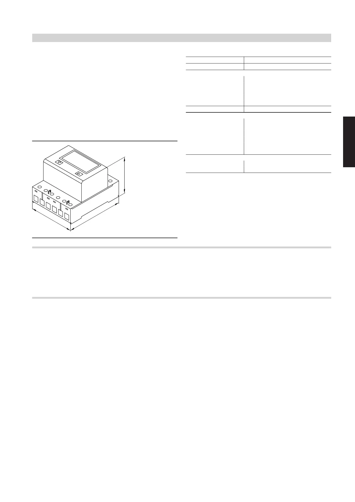
For optimised utilisation of the self-generated power from photovol-
taic systems (own energy consumption), the following components
and functions may be enabled by the Vitotronic control unit:
■ Heat pump compressor.
■ Heating of the DHW cylinder to the set DHW temperature or the
second set DHW temperature.
■ Heating the heating water buffer cylinder.
■ Central heating
■ Central cooling
Connection:
■ Installation on top-hat rail 35 mm (to EN 60715 TH35)
■
Main circuit cable cross-section: 1.5 to 16 mm
2
■
Control circuit cable cross-section: Max. 2.5 mm
2
Specification
Rated voltage
3 x 230 V~/400 V~
−20 to +15 %
Rated frequency
50 Hz
−20 to +15 %
Electricity
– Reference current 10 A
– Max. measurable cur-
rent 65 A
– Starting current 40 mA
– Min. current 0.5 A
Power consumption 0.4 W actual power per phase
Display
– Per phase: Actual pow-
er, voltage, current LCD, 7-digit, for 1 or 2 tariffs
– Count range 0 to 999999.9
– Pulses 100 per kWh
– Accuracy categories B as per EN 50470-3
1 as per IEC 62053-21
Permissible ambient temperature
– Operation −10 to +55 °C
– Storage and transport −30 to +85 °C
9.3 Remote control units
Information on Vitotrol 200-A
A Vitotrol 200-A can be used for each heating or cooling circuit.
The Vitotrol 200-A can operate 1 heating/cooling circuit.
Up to 3 remote control units can be connected to the control unit.
Note
Hardwired remote control units cannot be combined with the wire-
less base station.
Vitotrol 200-A
Part no. Z008341
KM-BUS subscriber
■ Displays:
– Room temperature
– Outside temperature
– Operating condition
■ Party and economy mode can be enabled via keys
■ Integral room temperature sensor for room temperature hook-up
(only for one heating circuit with mixer)
■ Settings:
– Set room temperature for standard mode (normal room tempera-
ture)
Note
The set room temperature for reduced mode (reduced room
temperature) is set at the control unit.
– Operating program
Installation location:
■ Weather-compensated mode:
Installation anywhere in the building
■ Room temperature hook-up:
The integral room temperature sensor captures the actual room
temperature and effects any necessary correction of the flow tem-
perature.
The captured room temperature depends on the installation site:
– Main living room on an internal wall opposite radiators
– Not on shelves or in recesses
– Never in the immediate vicinity of doors or close to heat sources
(e.g. direct insolation, fireplace, TV set, etc.).
Connection:
■ 2-core lead, length max. 50 m (even if connecting several remote
control units)
■ Never route this lead immediately next to 230/400 V cables
■ LV plug as standard delivery
Control unit accessories
(cont.)
VITOCAL
VIESMANN
137
5831388
9





 To Next Page