GB
General notice (liability): the details of this technical documents serve for description. Consents regarding the availability of certain features or
regarding a certain purpose always require a special written agreement.
Page No. 5237330-05 GB 3.6 Right reserved to make technical changes!
A2
BN
GNYE
BU
A2
L1
PE
N
A6
BN
GNYE
BU
A6
L1
PE
N
M
1
~
A5
BN
BK
BU
A5
3
2
1
P
214
A1
BK
GNYE
BU
A1
L1
PE
N
BN
T
Output 230 V/50 Hz
and door contact
A7
A7
BN
GNYE
BU
L1
PE
N
M
3
~
A9
Condens
A6
Oil
heating
A7
E1
Heating
230V / 50 Hz
A2
Defro
haeting
9 - pol.
D - Sub
5 x 1
A3
ext.
Alarm
E2
Temp.-
sensor
A1
Pressostat
Fuse Box
for FS 1800 SE
and FS 2400 SE
Evaproate
Vent
A4
A5
Multi-Pole
lead
230V / 50 Hz
Potential-free
Alarm
AC 10A/230 V
A3
A3
C
NC
NO
Liquely
Vent 1
A8
A8
BN
GNYE
BU
A8
L1
PE
N
M
1
~
A4
BN
GNYE
BU
A4
L1
PE
N
M
1
~
For FS 1800 SE and
FS 2400 SE CEE-
pre-installed plug
and fuse box
E1
E1
BN
GNYE
BU
L1
PE
N
Net filter
9 - pol
D - Sub
Socket
5 x 1
Serial
interface
E2
BN
BU
E2
2
1
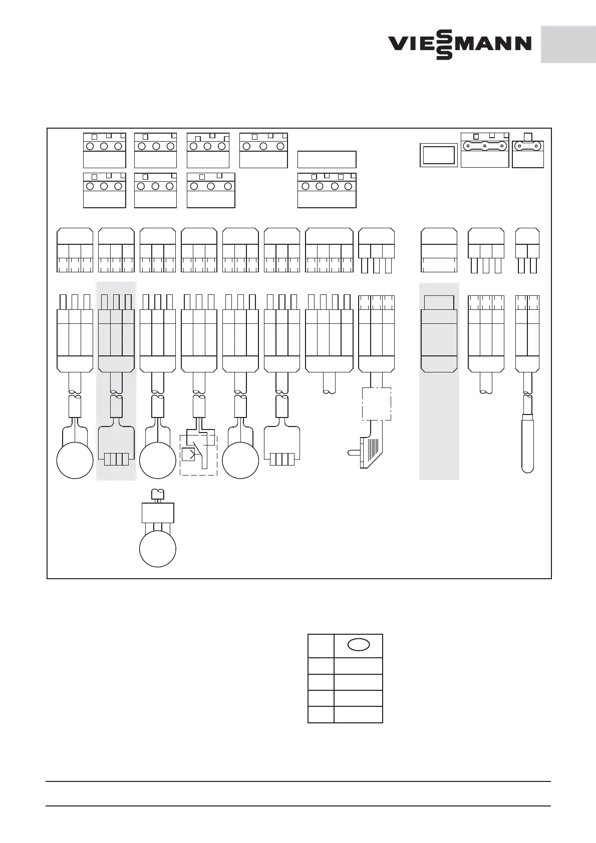
3.6 Plus connecting diagram for electronic regulator SE
A1 Plug 230 V / 50 Hz and door contact
A2 defroster heating
A3 Potencial-free alarm contact (s. Ch. 3.4)
A4 Evaporation ventilator
A5 Pressostat
A6 Condenser
A7 Oil heater (Option)
A8 Condenser ventilator
E1 Power supply 230 V / 50 Hz
E2 Coldroom temperature sensor
5 x 1 Option Interface
DIN/
IEC
GB
BK black
BN brown
BU blue
GNYE green/yellow
 Loading...