10
A
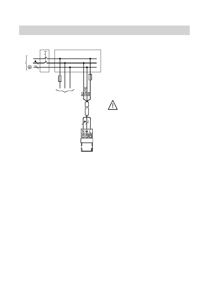
Power supply for extension
B
Power supply for heat generator
control unit
C
Power supply 1/N/PE, 230 V/50 Hz
D
Fuse (max. 16 A)
E
Mains isolator, 2-pole, on site
F
Junction box (on site)
Connect the power supply in accord-
ance with the diagram.
If the power supply to the appliance is
connected with a flexible cable, ensure
that the live conductors are pulled taut
before the earth conductor in the event
of strain relief failure. The length of the
earth conductor wire will depend on the
design.
Danger
Incorrect core assignment can
result in serious injury and dam-
age to the appliance.
Never interchange cores "L" and
"N".
!
Please note
Incorrect phase sequence can
cause damage to the appliance.
Ensure phase equality with the
power supply of the heat gener-
ator control unit.
Colour coding to IEC 60757
BN Brown
BU Blue
GNYE Green/yellow
Power supply
(cont.)
5831394