EasyManua.ls Logo

Viessmann EM-P1 User Manual

Viessmann EM-P1
16 pages
To Next Page IconTo Next Page
Page #1 background imageLoading...
Page #1 background image
5831394 GB 6/2018
Please keep safe.
Installation and service
instructions
for contractors
VIESMANN
EM-P1 extension
Function extension for connecting a heating circuit pump
Safety instructions
Please follow these safety instructions closely to prevent accidents
and material losses.
Safety instructions explained
Danger
This symbol warns against the
risk of injury.
!
Please note
This symbol warns against the
risk of material losses and envi-
ronmental pollution.
Note
Details identified by the word "Note"
contain additional information.
Installation, initial start-up, inspection,
maintenance and repairs must only be
carried out by a competent person
(heating engineer/installation contrac-
tor).
Before working on the equipment/heat-
ing system, isolate the power supply
(e.g. by removing a separate mains
fuse or by means of a mains isolator)
and safeguard against unauthorised
reconnection.
When using gas as fuel, also close the
main gas shut-off valve and safeguard
against unauthorised reopening.
Repairing components which fulfil a
safety function can compromise the
safe operation of your heating system.
For replacements, use only original
spare parts supplied or approved by
Viessmann.

Other manuals for Viessmann EM-P1

Question and Answer IconNeed help?

Do you have a question about the Viessmann EM-P1 and is the answer not in the manual?

Viessmann EM-P1 Specifications

General IconGeneral
BrandViessmann
ModelEM-P1
CategoryControl Unit
LanguageEnglish

Summary

Installation and Service Instructions

Safety Instructions

Essential safety guidelines to prevent accidents and material losses during installation and operation.

Safety Instructions Explained

Explanation of safety symbols and important notes for safe handling and operation.

Installation Procedures

Wall Mounting

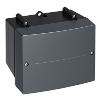
Instructions and diagrams for physically mounting the EM-P1 extension unit.

Overview of Electrical Connections

Diagram showing all electrical connection points and their labels for the EM-P1 extension.

Electrical Connections

Connecting the Immersion Temperature Sensor

Guide on how to connect the immersion temperature sensor to the EM-P1 extension.

Connecting the Heating Circuit Pump (230 V~)

Detailed instructions for connecting a 230 V heating circuit pump to the EM-P1 extension.

Heating Circuit Pump Connections (with Switching Input)

Pumps with Switching Input (230 V~ / 400 V~)

How to connect heating circuit pumps with switching input, including 230V and 400V variants.

Heating Circuit Pump Connections (without Switching Input)

Pumps Without Switching Input

Procedure for connecting heating circuit pumps that do not have a switching input.

Control and Communication

Rotary Switch S1 Setting

Instructions for setting the rotary switch S1 to the correct position for operation.

Connecting PlusBus

Procedure for connecting the PlusBus to the heat generator control unit.

Power Supply

Power Supply at Heat Generator Control Unit

Details on connecting the power supply directly to the heat generator control unit.

Separate Power Supply

Guidance for using a separate power supply for the EM-P1 extension.

Power Supply Safety Measures

Safety Regulations and Earthing

Regulations and safety measures for connecting the power supply, including earthing.

Isolator Requirements

Requirements for mains isolators and circuit breakers for non-earthed conductors.

Power Supply Connection Diagram

Connection Diagram and Color Coding

Diagram illustrating the correct power supply connection with color coding and safety notes.

Connection and Wiring Diagram

Comprehensive Wiring Diagram

Comprehensive wiring diagram showing all components and connections for the EM-P1 extension.

Parts List

Ordering Parts Details

Information required for ordering replacement parts, including serial and position numbers.

Parts List (Illustrations)

Parts List Illustrations

Visual representation of parts with corresponding numbers for easy identification.

Product Specification

Technical Specification Details

Technical specifications including voltage, current, power, IP rating, and operating temperatures.

Specification and Compliance

Immersion Sensor Temperature Curve

Graph showing the resistance-temperature relationship for the immersion sensor.

Declaration of Conformity

Statement confirming the product's compliance with European directives and national requirements.

Related product manuals