6
kWh
P
N
G
kWh
A
L
M
~
~
=
F
O
K
H
E
D
B C
R
Q
R
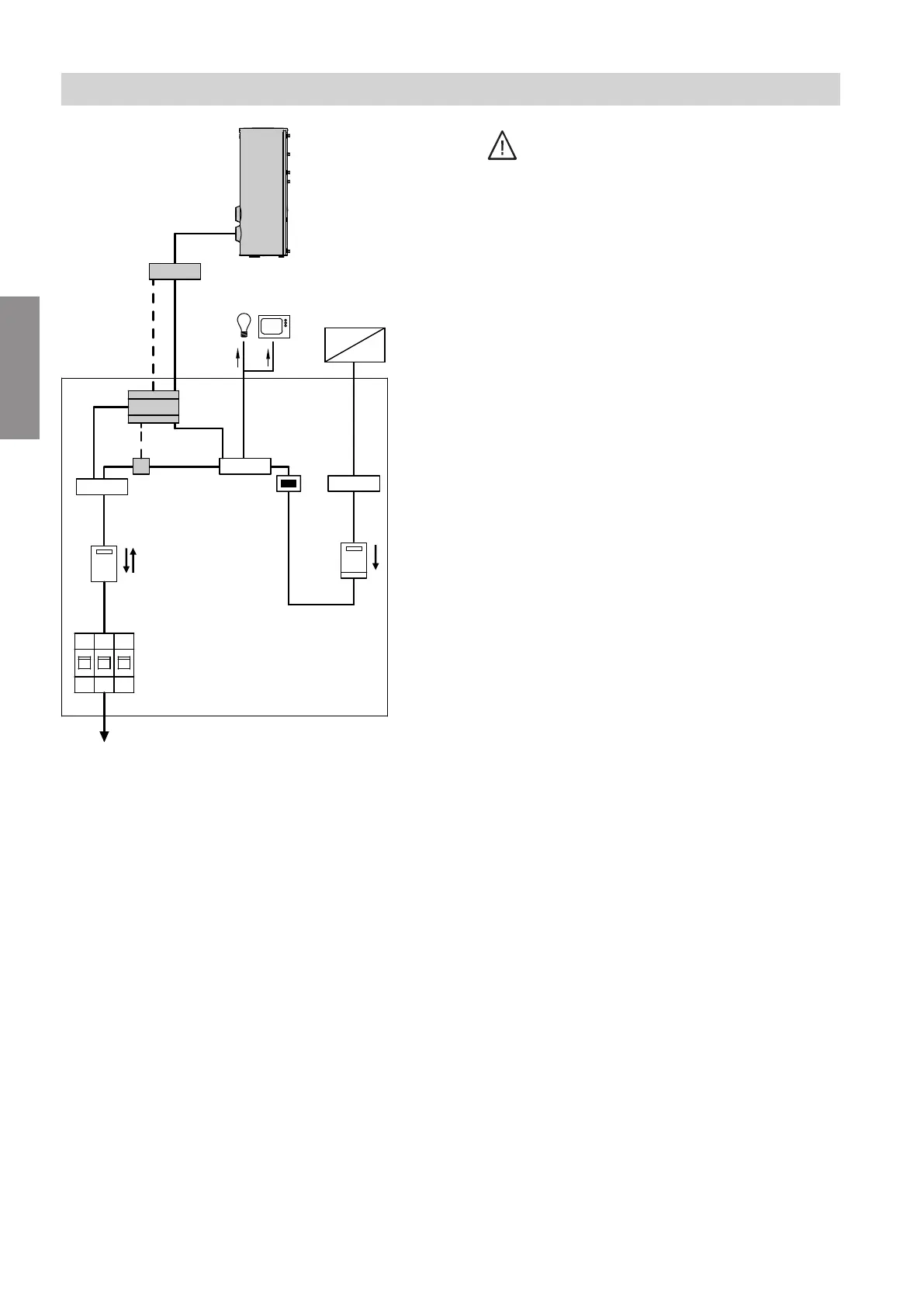
Fig. 1
A
Energy meter
B
Output control module
C
Vitocell 100-B DHW cylinder, type CVE
D
Terminal
E
Other consumers in the household that use on-site
generated power
F
Inverter
G
Isolator for the photovoltaic system
H
Terminal
K
Meter with reversing block:
For energy generated by the photovoltaic system
L
Distribution panel
M
To the domestic distribution box
N
Isolator for domestic power supply connection (dis-
tribution panel)
O
Bidirectional meter (for photovoltaic systems suita-
ble for utilisation of power generated on site):
Energy drawn from the grid (power supply utility)
and power exported to the grid (power supply util-
ity)
P
Terminal
Q
Current sensor
R
Control cable
1. Danger
When subject to insolation, PV modules can
generate life threatening voltages. Contact
with live parts (e.g. terminals) can lead to
burns and electric shock, even if the PV
modules are not connected.
■
First disconnect the inverter from the AC
grid (AC side of the inverter).
■
Then disconnect the DC isolator from the
DC grid (DC side of the inverter).
■
If required, cover PV modules with light-
proof films or fabrics.
■
Observe VDEW guidelines and technical
connection requirements of the grid opera-
tor.
2. Install energy meter on a mounting rail in the distri-
bution panel, see fig. 1.
Installation sequence
Installing the energy meter in the distribution panel
5678 581 GB
Installation
 Loading...