6
3. Electrical connections
NOTE The symbol marked on the cabinet (a lightning bolt inside a triangle) indicates
that there are components and wires under the cover containing live voltage.
Only personnel qualied to install and service electrical equipment are
permitted access to areas that contain live voltage.
Check the voltage and size of the fuse required from the rating plate xed to the cabinet. The
supply socket must be earthed. Fuse ratings for different types of plugs are presented in the
following table:
PLUG TYPE
16A Euro Schuko
13A BS 1363
16A CEE
32A CEE
2x16A Euro Schuko
2x13A BS 1363
3x16A CEE 3-Phase
No other appliances may be connected to the same fuse. The electrical connections for
the cabinet are shown in the wiring diagram in the plastic wallet attached to the side of the
electrical terminal box. Always replace the wiring diagram after use.
WARNING
All electrical connections must be carried out by approved and qualied
personnel and comply with all IEE and local regulations. Failure to do so could
result in personal or fatal injury.
NOTE
By default, the power cable of TectoPromo MD4 Visio is located on top of the
cabinet.
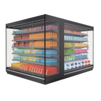
4. Operation
The cooling is achieved by a fan evaporator system. The evaporator is located at the bottom
of the cabinet’s tray. The cold air is blown to the shelves through the perforated back wall and
through the cooling cell in the top corner.
The cabinet is equipped with an electronic controller. In case the pressure rises to high, for
example because of dirt in the condenser, the controller stops the machine from running and
shows an error message (HA2).
On TectoPromo MD4 Visio, there is no separate switch for cabinet lights. The lights are
controlled by a button located on top left of the controller’s display panel. Please see the
picture on chapter Control device.
For more information on the control system, please see the corresponding chapters.
 Loading...