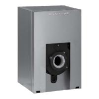
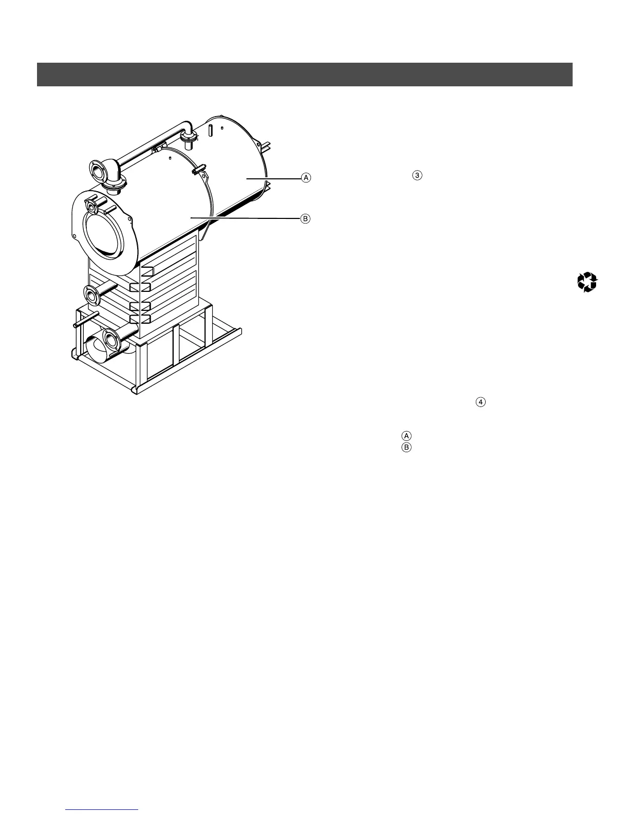
Fig. 2
Assembled combustion chamber shown
Viessmann Manufacturing Company Inc.
750 McMurray Road
Waterloo, Ontario • N2V 2G5 • Canada
Tel. (519) 885-6300 • Fax (519) 885-0887
www.viessmann.ca • info@viessmann.ca
Viessmann Manufacturing Company (U.S.) Inc.
45 Access Road
Warwick, Rhode Island • 02886 • USA
Tel. (401) 732-0667 • Fax (401) 732-0590
www.viessmann-us.com • info@viessmann-us.com
2
Assembly Instructions (continued)
5. Join front cone section with main
boiler section and ensure that a
gasket has been placed between the
water connection flanges. Tighten all
four bolts around the boiler section
and the flanges. Scrape off
excess silicone from the inside of the
combustion chamber with end of the
empty silicone tube.
6. Using a disposable latex glove (with
liquid soap or hand moisturizer), or
plastic trowel, and smooth silicone
strip on the inside of the combustion
chamber.
7. Remove tape (after approx. 4 hours)
by carefully pulling out tabs from the
combustion chamber.
Wash hands when finished.
Ensure that there are no gaps in the
silicone seal along the joint of the
two sections.
8. Install gaskets on common boiler
supply header
and tighten flanges
with the nuts and bolts provided.
Front cone section
Main boiler section
Printed on environmentally friendly
(recycled and recyclable) paper.
5285 410 v1.1
Technical information subject to change without notice.
Printed on environmentally friendly
(recycled and recyclable) paper.