Do you have a question about the Viessmann Vitocrossal and is the answer not in the manual?
Provides essential safety guidelines for working on the heating system.
Warns about burns from hot surfaces and fluids, advising to switch off and cool down before work.
Outlines safety procedures for operating the system under various conditions like gas or flue gas detection.
Warns about life-threatening poisoning from reverse flue gas flow due to simultaneous operation of boiler and exhaust appliances.
Details immediate actions to take if gas is detected, emphasizing explosion risk and evacuation.
Advises caution when repairing safety-critical components and using genuine Viessmann parts.
Provides instructions for responding to flue gas detection, highlighting poisoning risk and ventilation.
Advises on immediate actions for water leaks due to electrocution or scalding risks.
Emphasizes ensuring clear flue systems and adequate combustion air supply for safe operation.
Outlines the procedural steps for commissioning, inspecting, and maintaining the system.
Details the process of filling the heating system and verifying ventilation air supply.
Continues the troubleshooting flowchart for burner operation and fault identification.
Details the steps for checking gas pressures and implementing corrective measures.
Continues the procedure for checking additional pressure switches and provides safety notes.
Details how to remove the burner and inspect the burner door gasket for damage.
Continues the procedure for removing burners for 120-160 kW and 240-320 kW twin boilers.
Covers the removal and inspection of burners for boilers from 200 kW and twin boilers from 400 kW.
Explains how to check the burner gauze assembly for damage and contamination and reassemble.
Continues the procedure for checking burner gauze and thermal insulation for different kW ranges.
Details checking the burner gauze assembly for 200 kW units.
Covers torque values for reassembly and checking electrode gaps.
Covers reassembling flue connections and checking the flue gas damper and header.
Guides on checking and topping up the expansion vessel and system pressure.
Provides notes on using approved leak detection agents and removing residues.
Covers selecting upper/lower heating outputs for different control units.
Illustrates standard and reduced set room temperature adjustments and slope/level adjustments.
Details how to access the extended menu to adjust heating curves.
Illustrates the operational sequence and identifies potential faults with troubleshooting measures.
Explains how to test static and supply gas pressures, including safety precautions.
Explains the function of the pressure switch and how to check its response and related components.
Explains how to check, clean, and adjust ignition and ionisation electrodes.
Details checking gaskets on flue connections and heating water fittings for leaks.
Explains how to check flue gas dampers and headers for damage and leaks.
Details how to record water quality parameters and specifies requirements for hardness and pH.
Explains how to check CO2 or O2 content for optimal combustion quality.
Details how to select lower and upper heating outputs via the service menu.
Details how to check and record the gas type and Wobbe index for proper burner adjustment.
Explains how to call up and reset the service display for maintenance reminders.
Instructs to check all heating water and DHW connections for leaks.
Explains that the control unit must match system equipment level and components are recognized automatically.
Refers to previous pages for burner installation steps.
Describes adjusting heating curves based on outside and boiler water temperatures.
Emphasizes checking gas equipment for tightness due to explosion risk.
Details coding for temperature increases and durations for boiler water or flow temperature.
Explains coding for DHW priority, economy function, and heating circuit pump logic.
Explains how to perform an actuator test to control relay outputs and lists controllable actuators.
Lists controllable actuators (relay outputs) for system design.
Explains how faults are indicated on weather-compensated and constant temperature control units.
Explains how to access the 10 most recent saved faults.
Continues fault display info and explains how acknowledged faults are redisplayed if not remedied.
Lists fault codes related to coding cards, main PCB faults, and internal faults.
Explains how to access and select fault messages from the history.
Lists faults without specific display codes, their causes, and measures.
Details checking combustion quality via CO2/O2 content and the self-calibration process.
Explains how the electronic combustion controller uses ionisation current and air ratio for optimal combustion.
Details VDI Guideline 2035 and standard values for preventing scale build-up.
| Heat Exchanger Material | Stainless Steel |
|---|---|
| Category | Boiler |
| Efficiency | Up to 98% |
| Installation Type | Floor Standing |
| Boiler Type | Condensing |
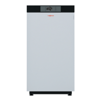
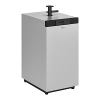
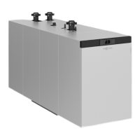
| Model | Vitocrossal |
| NOx Emissions | Low (class 5) |