29
Outdoor unit: Connecting the refrigerant lines
Note
For installing the refrigerant lines, embossing is provi-
ded at the various points in the casing:
■
Types 101.B04 to 101.B06:
The refrigerant lines can be routed out of the outdoor
unit to the back.
■
Types 101.B08:
The refrigerant lines can be routed out of the outdoor
unit to the right or to the back.
For easier installation of the refrigerant lines, the
"connection set for connection to the back of the out-
door unit" is included in the standard delivery.
■
Types 101.A12 to 101.A16:
The refrigerant lines can be routed out of the outdoor
unit to the right, to the back or to the bottom.
1. Undo the side cover: See page 48.
Open the embossing on the casing at the required
point. Insert the appropriate diaphragm grommet.
Note
Diaphragm grommets for sealing the opening for
the refrigerant lines are included in the standard
delivery of the indoor unit.
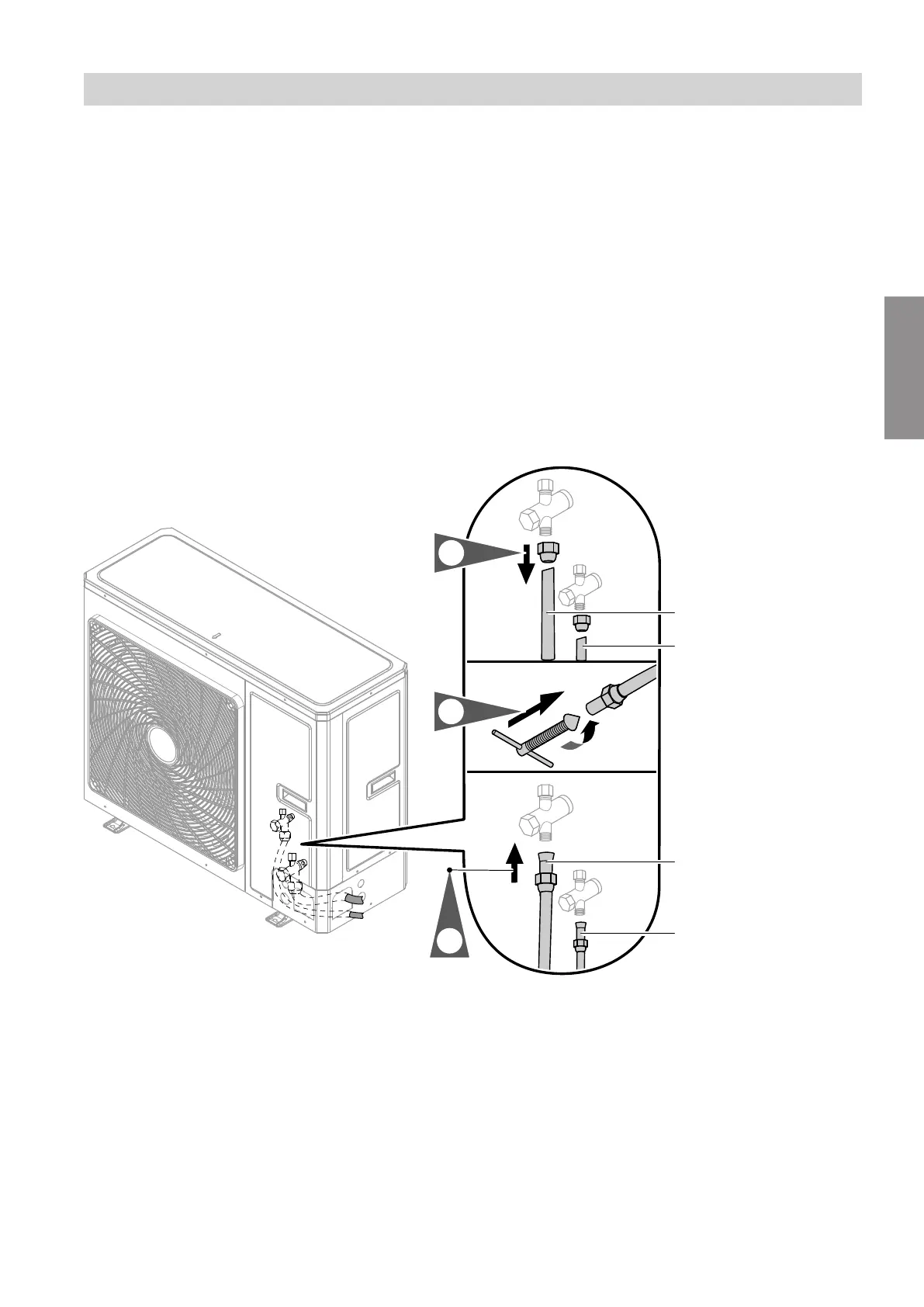
Fig. 23 Example: Type 101.B08
C
Liquid line:
■
Types 101.B04 to 101.B08:
7
6 mm for ¼ UNF
■
Types 101.A12 to 101.A16:
7
10 mm for ⅝ UNF
D
Hot gas line:
■
Types 101.B04 to 101.B08:
7
12 mm for ½ UNF
■
Types 101.A12 to 101.A16:
7
16 mm for ⅞ UNF
Installation sequence
Connecting the refrigerant lines (cont.)
6199585
Installation
 Loading...