48
A
[{S
DE
[{{]
0-10V
f-]
A
[{A
DE
[{D
DE
+ -5 63 41 21 2
B
L1N
H
L1
N
M
1~
C
D
F G
E
K
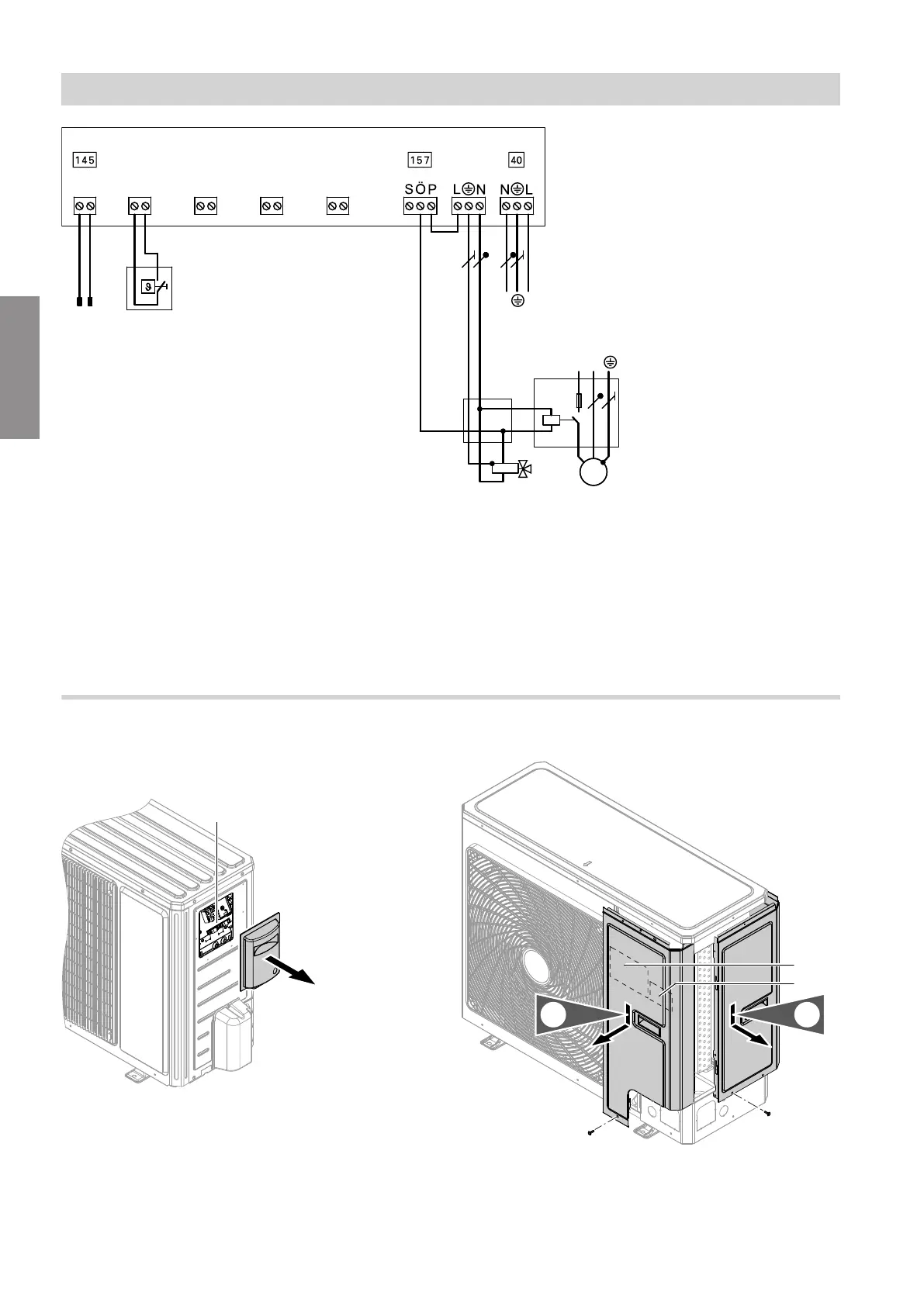
Fig. 41
A
EA1 extension
B
Power supply 1/N/PE 230 V/50 Hz
C
Junction box (on site)
D
Fuses and contactor for circulation pump for swim-
ming pool heating (accessories)
E
Jumper
F
3-way diverter valve for "Swimming pool" (zero
volt: heating the heating water buffer cylinder)
G
Circulation pump for swimming pool heating
(accessories)
H
Temperature controller for swimming pool temper-
ature control (floating contact: 230 V~, 0.1 A,
accessories)
K
Connection to controller and sensor PCB
Outdoor unit: Overview of connections
Outdoor unit with 1 fan: Open wiring chamber
Types 101.B04 to 101.B06
Fig. 42
A
Wiring chamber:
■
Modbus connection to the indoor unit
■
Compressor power supply
Type 101.B08
Fig. 43
A
Modbus connection to the indoor unit
B
Compressor power supply
Installation sequence
Electrical connection (cont.)
6199585
Installation