31
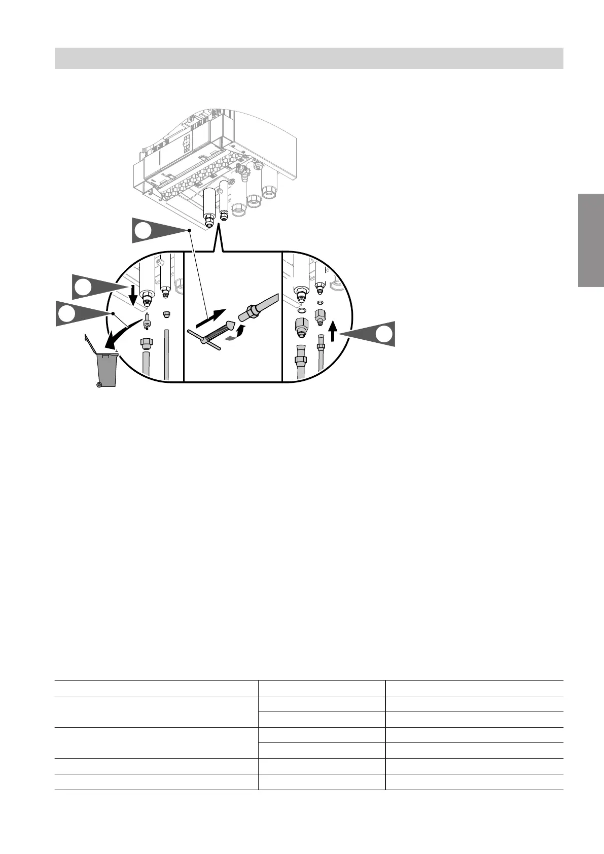
Indoor unit: Connecting the refrigerant lines
Fig. 24
C
Liquid line:
■
Types 101.B04 to 101.B08:
7
6 mm for ¼ UNF with reducer to ⅝ UNF
■
Types 101.A12 to 101.A16:
7
10 mm for ⅝ UNF
D
Hot gas line:
■
Types 101.B04 to 101.B08:
7
12 mm for ½ UNF
■
Types 101.A12 to 101.A16:
7
16 mm for ⅞ UNF
E
Schrader valve
F
Connector
!
Please note
Contamination (e.g. metal swarf) or moisture in
the copper pipes of the refrigerant lines will
cause the appliance to malfunction.
Point the pipe openings downwards or tempora-
rily plug them.
■
Deburr the cut ends of the pipes.
■
Types 101.B04 to 101.B08:
Flare the connections. Do not use solder fittings.
■
Only types 101.A12 to 101.A16:
If solder fittings are used, solder the fittings using a
shielding gas.
4. Apply thermal and vapour diffusion-proof insulation
to the refrigerant lines.
Torque for refrigerant lines
Cable Connection Torque in Nm
Liquid line 7 6 mm ⅝ UNF 33 to 42
¼ UNF 15 to 20
Hot gas line 7 12 mm ⅞ UNF 63 to 77
½ UNF 50 to 54
Liquid line 7 10 mm ⅝ UNF 33 to 42
Hot gas line 7 16 mm ⅞ UNF 63 to 77
Installation sequence
Connecting the refrigerant lines (cont.)
6199585
Installation
 Loading...