32
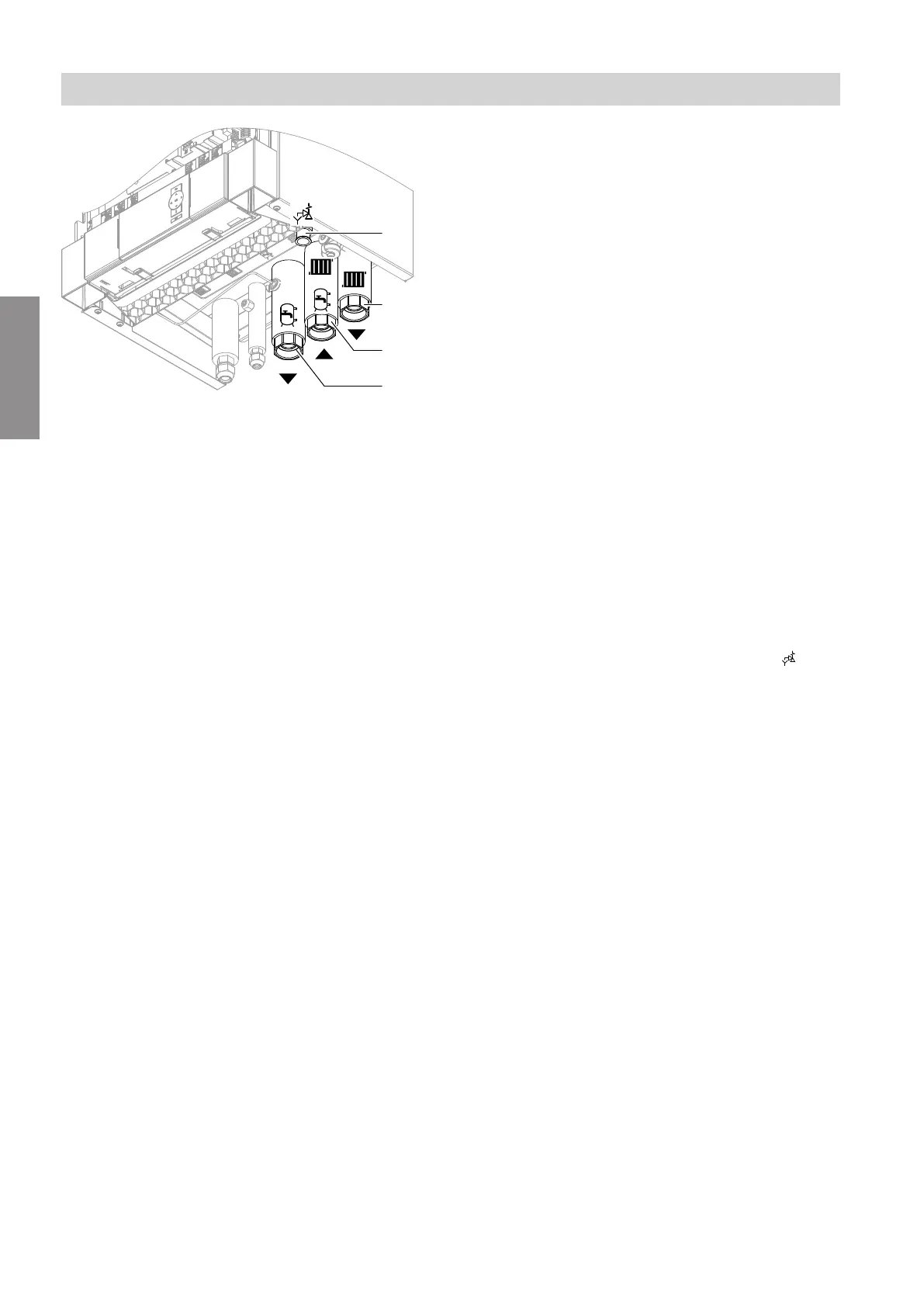
Fig. 25
A
DHW cylinder flow (heating water side): G 1¼
(female thread)
B
Heating water return and DHW cylinder return
G 1¼ (female thread)
C
Heating water flow: G 1¼ (female thread)
D
Safety valve drain hose
1. Connect the hydraulic lines to the heat pump.
!
Please note
Hydraulic connections subjected to mechani-
cal loads lead to leaks, vibrations and appli-
ance damage.
Connect on-site lines so that they are free of
load and torque stress.
2. Check the internal and on-site hydraulic connec-
tions for leaks.
!
Please note
Leaking hydraulic connections lead to appli-
ance damage.
■
Check the internal and on-site hydraulic
connections for leaks.
■
In the event of leaks, drain off liquid via the
drain valve. Check the seating of seal
rings. Always replace displaced seal
rings.
Note
The secondary circuit air vent valve is located
inside the appliance. To vent, connect the hose to
the air vent valve. Route the hose outwards.
Observe additional information regarding filling and
venting: See "Filling and venting on the secondary
side".
3. Thermally insulate lines inside the building. For
heat pumps with a cooling function, use thermal
and vapour diffusion-proof insulation.
4. Connect the drain hose of the safety valve to the
drain network with a fall and a pipe vent.
Note
■
With underfloor heating circuits, install a temperature
limiter to restrict the maximum temperature of under-
floor heating systems.
■
Ensure the minimum flow rate, e.g. by means of an
overflow valve: See "Specification".
Installation sequence
Connecting the secondary circuit
6199585
Installation
 Loading...