46
Terminals Function Explanation
■
With heat pump cascades
–
Power supply without on-site load disconnect:
Only connect the power-OFF signal to the lead heat
pump.
–
Power supply with on-site load disconnect: Con-
nect the power-OFF signal to all heat pumps.
■
For further information regarding power-OFF: See
chapter "Power supply".
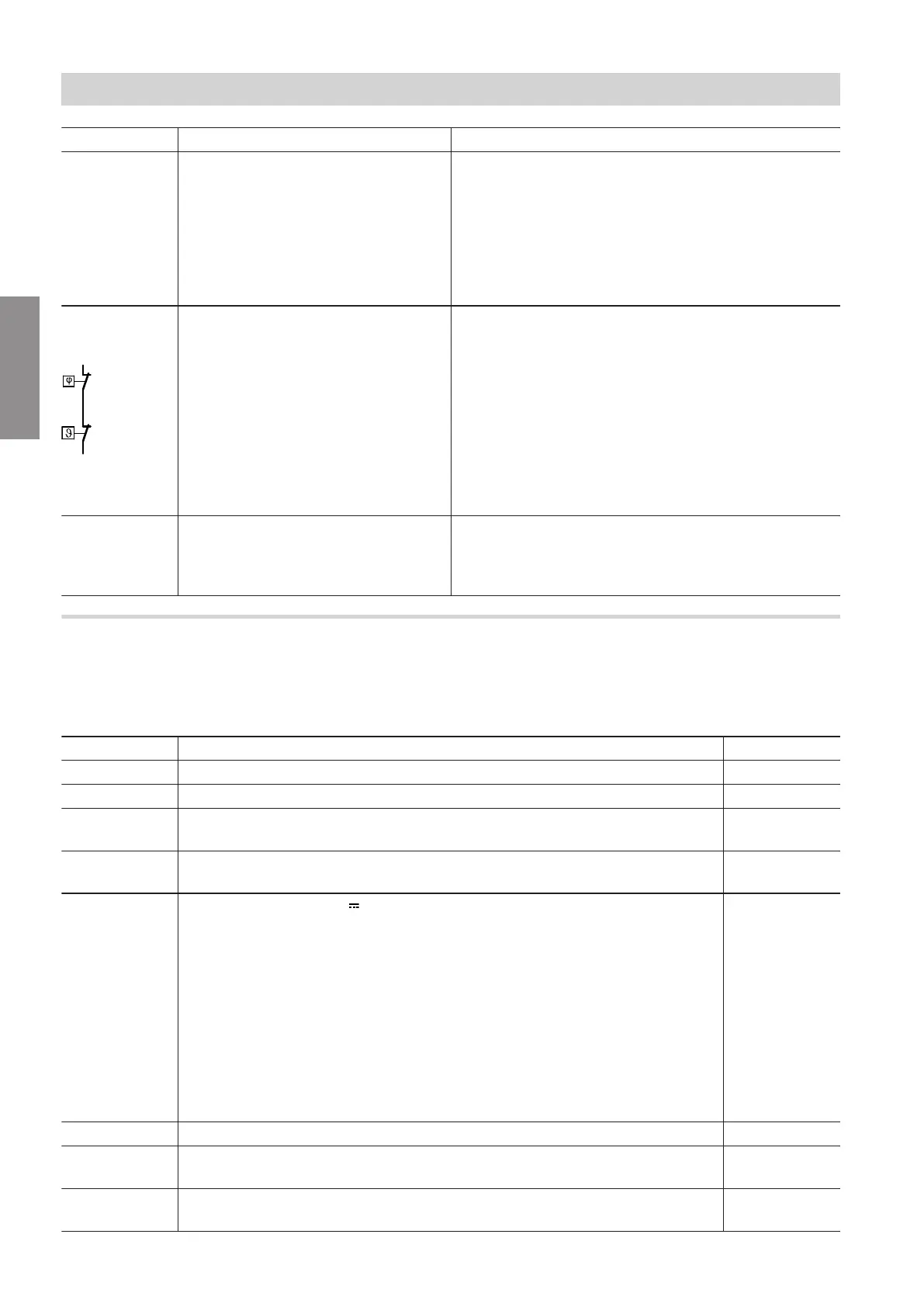
X3.8
X3.9
Only for heat pumps with a cooling
function:
■
Frost stat
and/or
Contact humidistat 230 V~
■
Or jumper
For heat pumps without a cooling
function:
■
Jumper
Requires floating N/C contact:
■
Closed: Safety chain has continuity
■
Open: Safety chain interrupted; heat pump not opera-
tional
■
Breaking capacity 230 V~, 0.15 A
Connection:
■
Connected in series if both safety components are in-
stalled
■
Insert jumper if no safety components are instal-
led.
X40.L1 Heat pump control unit power supply:
Phase L1
X40.? Earth conductor terminal
X40.N Neutral conductor terminal
Power supply 230 V~
Indoor unit: Controller and sensor PCB (extra low voltage (ELV) connections)
Set the required parameters during commissioning:
See page 67 onwards.
Sensors
Plug Sensor Type
F0 Outside temperature sensor NTC 10 kΩ
F4 Buffer temperature sensor NTC 10 kΩ
F6
(X25.5/X25.6)
Top cylinder temperature sensor NTC 10 kΩ
F7
(X25.7/X25.8)
Cylinder temperature sensor, bottom NTC 10 kΩ
F11 Contact humidistat 24 V
Or jumper
Note
■
System with heating water/coolant buffer cylinder:
If cooling is performed via several heating/cooling circuits, provide a contact
humidistat for each heating/cooling circuit.
Connect several contact humidistats in series.
■
If a 230 V~ contact humidistat (connection to X3.8/X3.9) is used for cooling,
insert a jumper, otherwise the heat pump will not start (message "CA Pro-
tectn device primry").
―
F12 Flow temperature sensor, heating circuit with mixer M2/HC2 NTC 10 kΩ
F13 System flow temperature sensor (downstream of the buffer cylinder and mix-
er for external heat generator)
NTC 10 kΩ
F14 Flow temperature sensor, cooling circuit (heating circuit without mixer A1/HC1
or separate cooling circuit SKK)
NTC 10 kΩ
Installation sequence
Electrical connection (cont.)
6199585
Installation