54
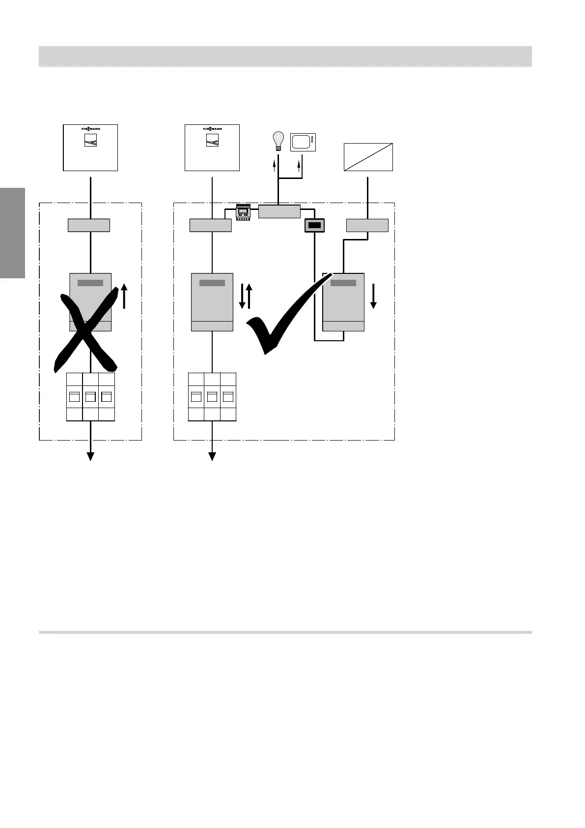
Mains power supply in conjunction with on-site power consumption
Without power-OFF
kWh
G
F
L
kWh
F
L
E
kWh
N E1E2 D /D
L1 L1 L2 L2 L3 L3
C
A
M
NN
A
~
~
=
D
H K
M
F
B
F
Fig. 47
A
Heat pump
B
Additional consumers (of power generated on site)
in the household
C
Electricity meter
D
Inverter
E
Isolator for the PV system
F
Terminal
G
Double-tariff meter (for special tariff for heat pump)
Not permissible in conjunction with PV systems for
on-site power consumption
H
Bi-directional meter (for PV systems to consume
power on site):
Energy taken from power supply utility and energy
fed into power supply utility
K
Meter with reverse block:
For energy generated by PV system
L
Isolator for the domestic power supply connection
(distribution panel)
M
Distribution panel
N
Domestic distribution box
Smart Grid
The Smart Grid functions are switched via the two
PSU floating contacts.
Connection options for the two floating contacts:
■
To EA1 extension as shown in Fig. 48
■
To the heat pump control unit as shown in Fig. 49
Installation sequence
Power supply (cont.)
5831412
Installation
 Loading...


