55
Connection to EA1 extension
Condition: "Enable Smart Grid 7E80" must be at "1".
A
[{S
DE
[{{]
0-10V
f-]
A
[{A
DE
[{D
DE
+ -5 63 41 21 2
E
L1N
CB D
Fig. 48
A
EA1 extension
B
Connection to controller and sensor PCB
C
Floating N/O contact 1: The agreement of the
power supply utility may be required
D
Floating N/O contact 2: The agreement of the
power supply utility may be required
E
Power supply 1/N/PE 230 V/50 Hz
Note
■
If Smart Grid is enabled ("Enable Smart Grid 7E80"
set to "1"), both inputs DE2 and DE3 cannot be
used for signals "External demand" or "External
blocking".
■
The power-OFF function is integral to Smart Grid.
Therefore do not connect the power-OFF signal to
terminals X3.6 and X3.7. Do not remove jumper.
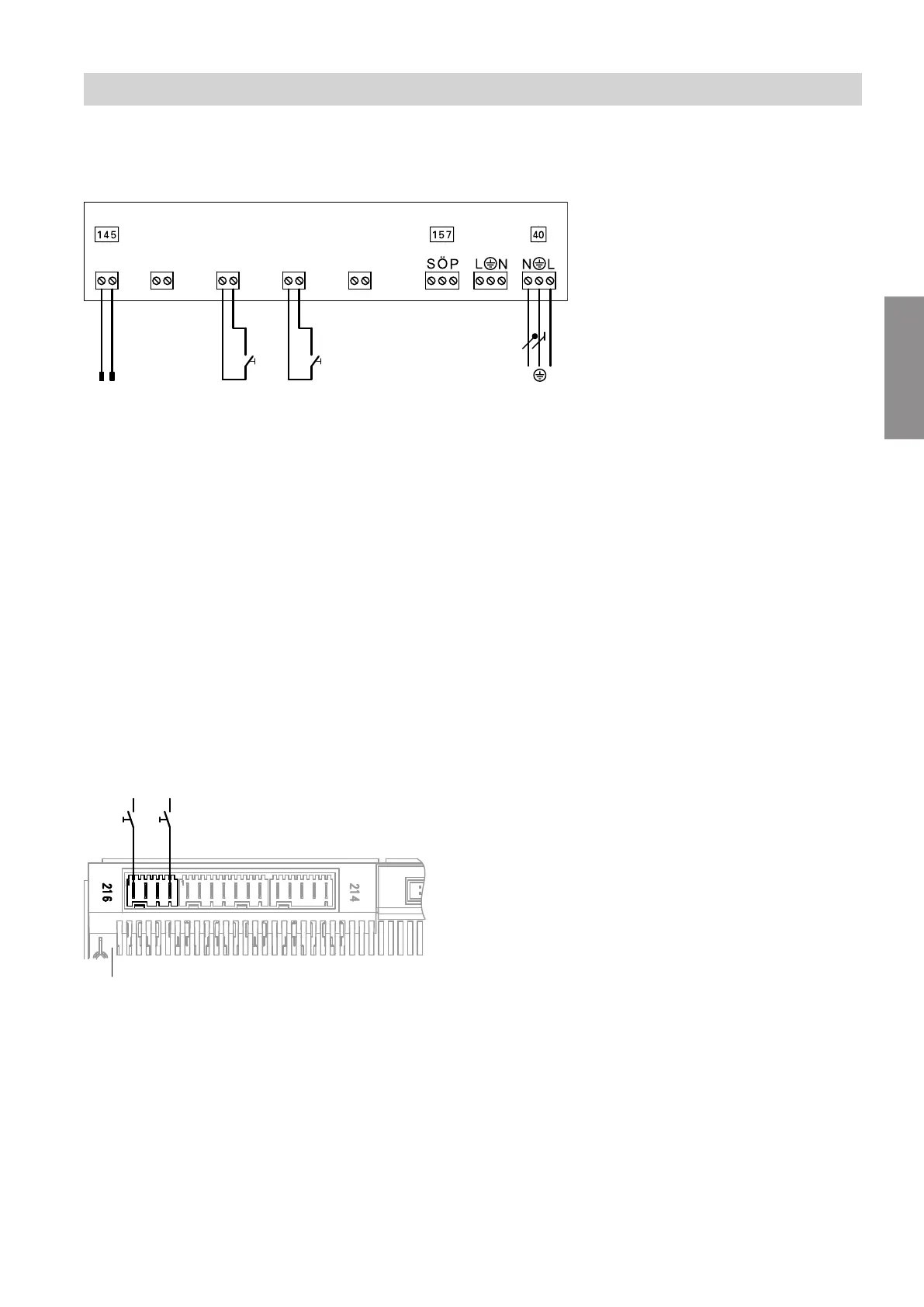
Connection to heat pump control unit
Condition: "Enable Smart Grid 7E80" must be at "4".
Fig. 49
A
Main PCB
B
Connection X3.1 (L') on the luster terminals
C
Floating contact 1: The agreement of the power
supply utility may be required
D
Floating contact 2: The agreement of the power
supply utility may be required
Note
■
If Smart Grid is connected to the two digital inputs on
main PCB ("Enable Smart Grid 7E80" set to "4"),
the external hook-up for the heating/cooling circuits
must not be switched on ("Remote control 2003"
set to "2"). Otherwise the Smart Grid will not be
active.
■
The power-OFF function is integral to Smart Grid. In
this case, therefore, the power-OFF signal must not
be connected to connections X3.6 and X3.7.
Installation sequence
Power supply (cont.)
5831412
Installation