7
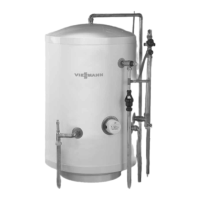
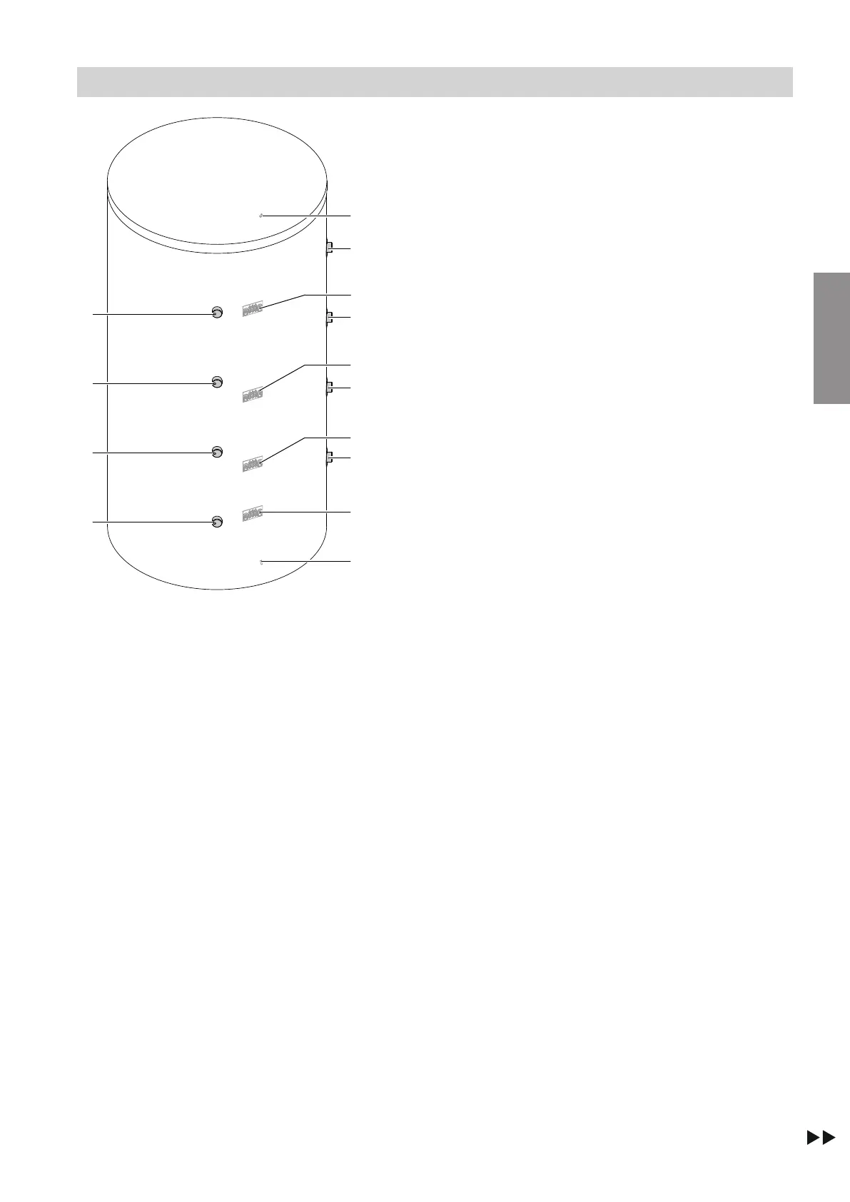
Fig. 1 Back
A
Heating water flow 1
B
Heating water flow 2/heating water return 1
C
Heating water return 2
D
Heating water return 3
E
Mounting for thermometer sensor (below thermal
insulation)
F
Clamping system for cylinder temperature sensor
1 (behind thermal insulation)
G
Mounting for thermometer sensor (below thermal
insulation)
H
Clamping system for cylinder temperature sensor
2 and thermometer sensor (behind thermal insula-
tion)
K
Clamping system for cylinder temperature sensor
3 and thermometer sensor (behind thermal insula-
tion)
L
Clamping system for cylinder temperature sensor
4 (behind thermal insulation)
M
Mounting for thermometer sensor (below thermal
insulation)
Preparing for installation
Connections
6153974
Installation