9
Note
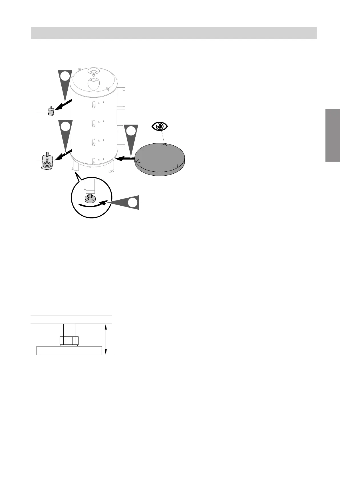
Seal connections that are not required with caps.
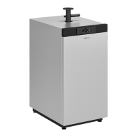
Fig. 2
A
Type plate
B
3 adjustable feet
3. Insert the adjustable feet into the legs as far as
they will go. Use the adjustable feet to level the cyl-
inder body.
Note
Only use one or two of the adjustable feet to level the
cylinder body. At least one of the adjustable feet must
remain fully screwed in.
Fig. 3
Do not extend the adjustable feet beyond a total
length of 35 mm.
Installation sequence
Levelling the heating water buffer cylinder
6153974
Installation