21
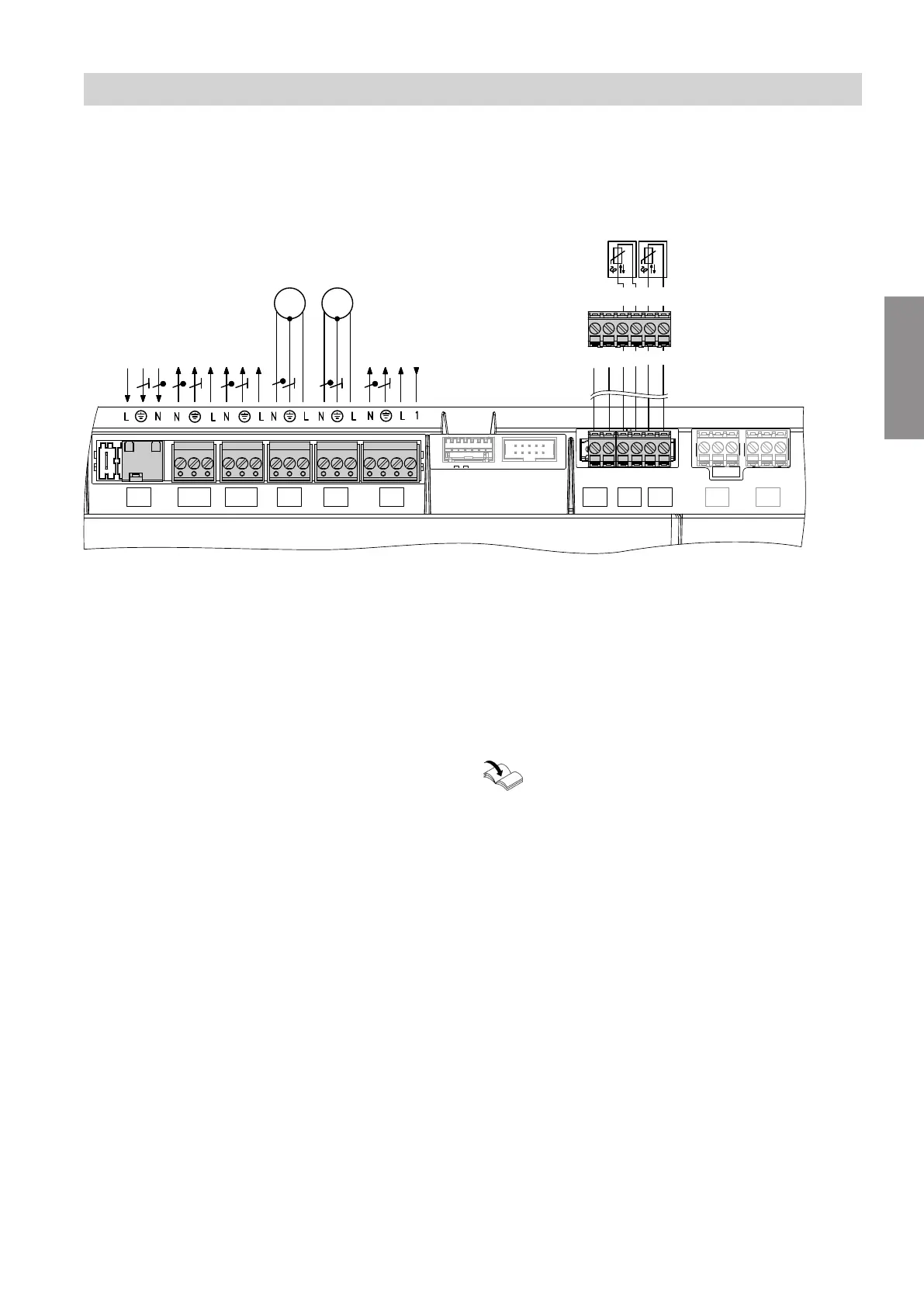
Layout of the electrical connections
Note
For further information on the connections, see the fol-
lowing chapters.
C
6 5 4 3 2 1
6 5 4 3 2 1
A B
1~
M
1~
M
5
40
156 156
96
74 1 91 915P2P1
Fig. 14
Connections to 230 V~ plugs
fÖ
Power supply
lH
Configurable input 230 V, potential free
Output 230 V
aBH
Switched power outlet
P1 Output 230 V for:
Circulation pump for cylinder heating or heating
circuit pump for heating circuit without mixer
P2 Output 230 V for:
Heating circuit pump for heating circuit without
mixer or DHW circulation pump
A
BCU burner control unit power supply (connected
in the delivered condition)
B
Power supply for accessories
C
External plug on underside of appliance (see dia-
gram below)
Connections to extra low voltage (ELV) plugs
!
Outside temperature sensor
Terminals 1 and 2 on external plug
C
%
Cylinder temperature sensor
Terminals 3 and 4 on external plug
C
jF
PlusBus
Terminals 5 and 6 on external plug
C
lA
CAN bus
Information on connecting accessories
When connecting accessories observe the sep-
arate installation instructions provided with
them.
Installation sequence
Electrical connections (cont.)
6131235
Installation
 Loading...