Do you have a question about the Viessmann VITODENS 200-W WB2B 80 and is the answer not in the manual?
Installation, service, and maintenance must be performed by a licensed professional.
Read all applicable documentation before installation and store it accessibly.
Improper installation can cause flue products with carbon monoxide to enter living space.
Never operate the boiler without a properly installed venting system.
Failure to follow documentation renders warranty null and void.
Familiarize the owner with operation, safety, and shutdown procedures.
Installation must comply with local codes and national standards like NFPA 70.
Ensure the system operator is familiar with operation, activation, and shutdown.
Start-up must be performed by a qualified heating contractor.
Installation, service, and maintenance must be done by a licensed professional.
Simulate fault by closing boiler valve and jumping flow switch.
Throttle boiler valve to minimum flow, run at high fire.
Remove wire from limit switch to create fault.
Note symbols like WARNING, CAUTION, and IMPORTANT for hazards and product info.
Lists special items, testing equipment, and cleaning supplies required.
Provide the boiler serial number when ordering replacement parts.
Details for models WB2B 80 and WB2B 105 for NG/LPG and NG only.
Ensure proper ambient temperatures and avoid contaminated combustion air.
Lists areas and products that can contaminate combustion air.
Considerations for boilers installed in damp, salty coastal areas.
Procedure to remove air from the boiler heat exchanger.
Steps to fill and reassemble the condensate siphon.
Procedure to fill the heating system with water and check pressure.
Verify voltage range and neutral conductor for boiler control.
Instructions for setting the current time and date on the control unit.
How to change the language displayed on the control unit.
Ensure the correct gas type (natural gas or LPG) is selected for operation.
Procedure to convert the boiler for operation with liquid propane gas.
Instructions for replacing coding cards for higher altitudes.
Procedures for measuring static and running gas supply pressures.
Flowchart of normal start-up and common fault codes encountered.
How to limit the maximum heating output via the modulation range.
Ensure all primary and secondary circuit connections are pressure tight.
Importance of CO measurement before and after gas appliance work.
Performing a simplified leak test on the venting system.
Step-by-step instructions for safely removing the burner assembly.
Inspect and replace burner refractory ring and cylinder assembly if needed.
Check and adjust electrode gaps for optimal ignition and flame detection.
Procedure for cleaning the internal surfaces of the boiler.
Ensure the siphon trap and drain are clear for condensate flow.
Verify pH of condensate and replace granulate if necessary.
Verify nitrogen pressure and system fill pressure.
Verify operation of low water cut-offs, pressure relief valve, and pumps.
Ensure all plug-in connectors are secure and properly seated.
Perform leak tests on gas supply piping before operation.
Measure CO2 and O2 content at the vent pipe adaptor for optimal combustion.
Verify boiler input by measuring gas meter performance.
Overview of the control unit's features, buttons, and displays.
Identifies buttons, displays, and their functions on the control unit.
Explains space heating, DHW, and electronic combustion control modes.
Details on ionization current, air factor, and combustion quality measurement.
Overview of different heating system configurations and corresponding coding addresses.
How to adjust the heating curve for optimal performance based on outdoor temperature.
Adjusting the slope parameter (d3) of the heating curve.
Adjusting the shift parameter (d4) of the heating curve.
Adjusting day temperature setpoints for heating circuits.
Adjusting night temperature setback values.
Instructions for integrating the boiler control into a LON communication system.
Process for updating the list of participants in a LON network.
Steps to verify communication and presence of LON participants.
Installer's responsibility to train the end-user on system operation.
Procedure for managing maintenance intervals and service messages.
Steps to enter and navigate coding level 1.
Procedure to enter coding level 1 using specific button combinations.
Details on system design, temperature limits, participant numbers, and DHW priority.
Settings for summer setback, supply temperatures, slope, and shift.
Steps to enter and navigate coding level 2.
Procedure to enter coding level 2 using specific button combinations.
Parameters for system design, boiler/burner functions, and intervals.
Settings for pump control and external signals (demand, blocking).
DHW settings, boiler status, and operational modes.
DHW settings, recirculation pumps, and LON communication.
General settings, fault display options, and calibration.
General settings, mixing valve circuits, and DHW priority.
Mixing valve circuits, economy functions, and frost protection.
Mixing valve circuits, room influence, supply temperatures, slope, and shift.
Mixing valve circuits, heating program changeover, and reduced temperature settings.
Procedure to restore all coding addresses to their original factory settings.
List of functions accessible via service level and their respective key combinations.
How to view system temperatures, coding card data, and brief scan values.
View system temperatures, coding card data, and brief scan values.
Procedure to test boiler outputs like pumps, valves, and burner status.
How to view real-time operating data and sensor readings.
Understanding fault messages, indicators, and codes on the control unit.
Identify fault indicators, fault codes, and plain text fault displays.
Steps to review, acknowledge, and clear fault messages.
How to access acknowledged fault messages and fault history.
Comprehensive list of fault codes, their causes, and corrective actions.
Further fault codes, system behaviors, causes, and corrective actions.
More fault codes related to communication, sensors, and control modules.
Fault codes related to ionization current, flame signal, and calibration issues.
Fault codes for high limit switches, fan issues, gas valves, and interference.
Procedures for diagnosing and fixing common boiler issues.
Procedure for testing the resistance of the outdoor temperature sensor.
Procedures to test boiler, tank, and supply temperature sensors.
Continued sensor resistance checks and replacement advice.
Procedure for testing the flue gas temperature sensor.
Procedure to test and replace a faulty fixed high limit switch.
Locating and checking fuses in the boiler and power/pump module.
Verifying the rotational direction of the mixing valve motor.
Instructions on how to reverse the mixing valve motor's rotation.
Details on external signals affecting heating programs and pumps.
Configuration for external signals to change heating programs.
How external blocking signals affect circulation pumps.
How external heat demand signals affect circulation pumps.
Descriptions of air bleed, fill, and temperature raising programs.
Description of the automatic air bleeding sequence.
Description of the system filling program.
How reduced room temperature setpoints are automatically raised.
Adjusting heat-up time and configuring remote control DIP switches.
Adjusting parameters to speed up transitions between heating modes.
Configuration of DIP switches for the Vitotrol 300 remote control.
Detailed breakdown of the burner's start-up, operation, and shutdown phases.
Complete schematic of electrical connections for the boiler system.
Explanation of symbols, component labels, and wire colors used in the diagram.
Explanation of symbols, component labels, and wire colors used in the wiring diagram.
List of components for NG Only and NG/LPG models, with part numbers.
Continued parts list with exploded views and part numbers.
Continued parts list with control console and accessory components.
Table for recording service dates, measurements, and setpoint values.
Table for recording service dates, measurements, and setpoint values.
Specifications for Boiler Model WB2B 80 and 105, including gas input, output, and pressures.
Continued technical specifications including dimensions, flue gas, and condensate data.
Critical safety precautions regarding fire, explosion, and gas leaks.
Step-by-step guide for starting and operating the boiler safely.
Procedure for safely shutting off the gas supply to the boiler.
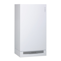
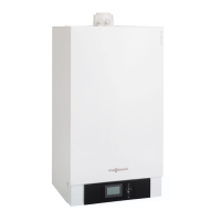
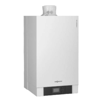
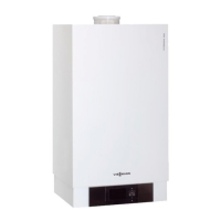
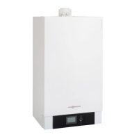
| Model | VITODENS 200-W WB2B 80 |
|---|---|
| Category | Boiler |
| Efficiency | Up to 98% (Hs) / 109% (Hi) |
| Fuel Type | Natural gas or LPG |
| Installation | Wall-mounted |
| Modulation Range | 1:6 |
| Water Pressure (max) | 3 bar |
| Type | Condensing Boiler |
| Control | Vitotronic control system |
| Water Temperature Range | 30 to 85 °C |
| Noise Level | 45 dB(A) |





 Loading...