9
A
Z
O
C
rR
1
rZ
Z
AO
C
6 2 wTwZ
rT
4
3wP
wUwI
wWwQqQqW
rE
qPqW
rW rQ
rR
qT
wR
wE
rP
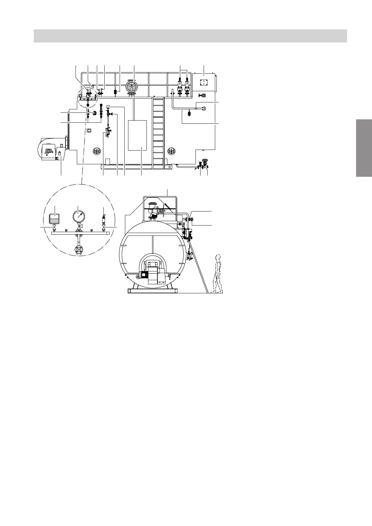
Fig. 1 Example installation diagram. Standard deliv-
ery may vary subject to order.
Note
CE-approved boiler with accessories fitted on site.
Standard delivery may vary subject to order.
1
Boiler control platform with conductor (optional)
2
Control panel (see separate documentation)
3
Integral ECO (subject to boiler size) (optional)
4
Connection line ECO - boiler (optional)
6
Burner
qP
Level electrode (WLC: Water level controller)
qQ
Level electrode (HWL: Highest water level)
qW
Level electrode (LWL: Lowest water level)
qT
Conductivity electrode
wP
Safety valve (number is country-specific)
wQ
Air vent shut-off valve (optional)
wW
Steam shut-off valve
wE
Feedwater shut-off valve
wR
Feedwater check valve
wT
Blow-down shut-off valve
wZ
Blow-down valve
wU
Desalination shut-off valve
wI
Desalination control valve
rP
Water level indicator
rQ
Pressure gauge
rW
Maximum pressure limiter
rE
Pressure transducer
rR
Straight-through shut-off valve with cap (optional)
rT
Temperature indicator for feedwater
rZ
Sample cooler
Note
Illustration of fitting assembly
rQ
to
rR
, applies to mod-
ulating operation. For stepped operation, provide the
required number of pressure regulators in place of the
pressure transducer.
Functions
Installation overview
5837984
Functions





 To Next Page