ViewSonic Corporation
Confidential - Do Not Copy VP2650wb-1
25
R612
47
Q601
2SK3548-01SC
D
G
S
D605
LL4148
A K
D603
LL4148
AK
D604
LL4148
AK
+
C611
47U 50V
12
+
C606
47U 50V
12
R623
4.7 J
ZD 601
TZMC15
A K
D608
RSX101VA-30
A K
D609
RSX101VA-30
A K
D610
RSX101VA-30
A K
+
C711
470U 35V
12
D611
UF 4007-LF
A K
R607
68K
R617
10K J
R613
1K J
R619
18K
C613
0.1U K
C607
680P K
D703
Y G865C15R
A1
J
A2
D702
Y G865C15R
A1
J
A2
D701
Y G865C15R
A1
J
A2
C709
1000P K
C710
1000P K
‧
IC 601NCP1203P40G
HV
8
NC
7
DRV
5
VCC
6
GND
4
CS
3
FB
2
ADJ
1
E5
R603
10K
R706
10
R705
10
R609
1M F
R611
150 J
R615
0.22
IC702
KA431AZTA_NL
A K
R
R608
1M F
C610
1000P K
C609
1000P K
R713
10K
L611
Z45/100MHZ
R614
18K
R610
18K
C716
0.1U K
IC602
PC123FY 1J00F
12
43
R712
2K
T601
540UH
2
3
7
9
1
5 8
10
D602
EGP10D-LF
AK
A11
N5
A12
D601
UF4007-LF
A K
R714
1K J
R716
28K F
R715
2.61K F
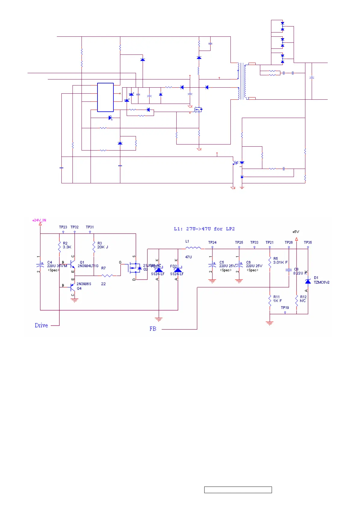
A-5.) Buck Converter(MCU, USB, Audio, Panel Power section)
Fig.A
Fig.A shows the typical Buck Converter circuit. Q2 s a switching device, and Q1, Q4 are the
totem pole which get enough ability to drive P-MOS. When the Gtae of Q2 is low level, Q2
turns on. At high level, Q2 turns off. The pulse waveform will appear at D-terminal of Q2. L1,
C5, C6, and D1 will transfer the pulse to stable DC level.
The feedback circuit is composed of two resistors R5 and R11, and feedback the DC level
1.25V with error signal. C8 is a compensation capacitor.

 Loading...