ViewSonic Corporation
Confidential - Do Not Copy VP2650wb-1
56
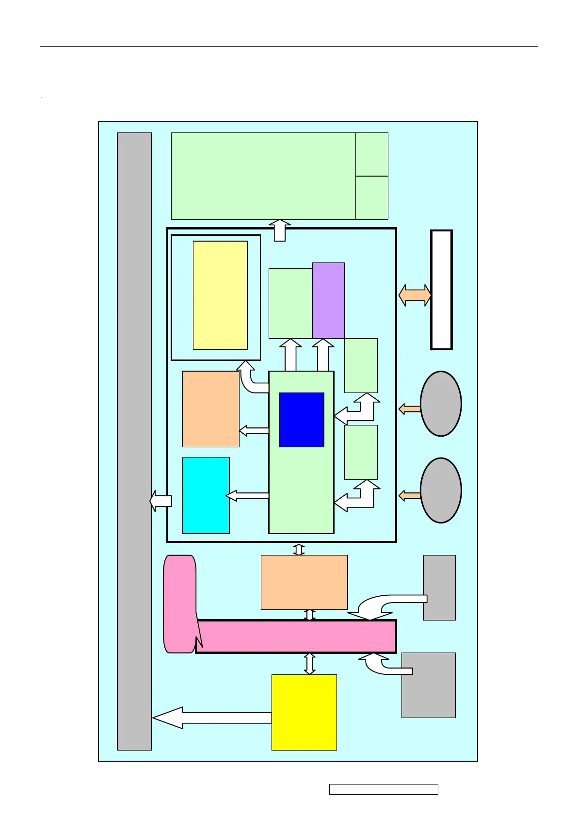
7. Block Diagram
The VP2650wb consists of a main body and a stand (base). The main body contains a CPT TFT LCD
module with 6 CCFL tubes (include inverter BD), a power board (includes AC/DC), DC-DC BD. and a
control board and an interface board and a USB board. The block diagram is shown as below.
CPT TFT-LCD module with 6 CCFL tubes
Genesis
Gm5862H
LVDS
Transmitte
r
EEPROM 24C16
MCU
Flash
ROM
Control Board D-Sub
AC
Switch
AC IN
DVI
0x600~0x6F0
HDCP area
A-DDCD-DDC
SDRAMx2
OSD Pivot o
USB BD.
1 UP/
4 Down
(Include
One
DC-DC
Circuit
24V to
5V for
USB)
1 UP 4 DN
Inverter
BD.
Power BD.
DC-
DC
BD.
 Loading...