V1.0 Vig644M Motherboard Manual
Motherboard Connectors
There are connectors on the motherboard for the Power supply, HD audio, fans, front
panel audio, front panel USB ad front panel connectors. The location and/or details of
these connections are shown below.
Front Panel Connectors
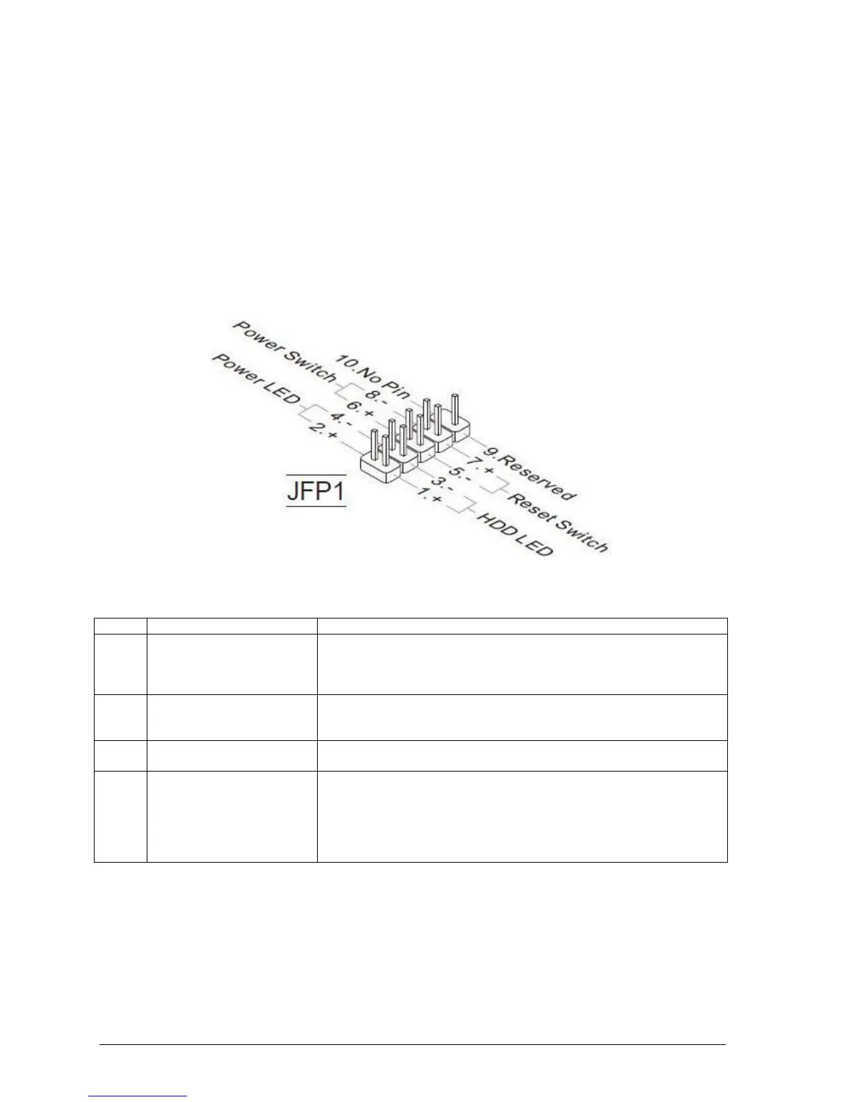
Front Panel Connectors: JFP1
These connectors are for electrical connection to the front panel switches and LEDs. The
JFP1 is compliant with Intel® Front Panel I/O Connectivity Design Guide.
Figure 6: Front Panel Connectors
Table 3: Front Panel Connectors (JFP1)
Hard Drive Activity LED
Header
Pins 1 and 3 can be connected to an LED to provide a visual
indicator that data is being read from or written to a hard drive.
Proper LED function requires a Serial ATA hard drive connected to
an onboard Serial ATA connector.
Pins 5 and 7 can be connected to a momentary single pole, single
throw (SPST) type switch that is normally open. When the switch is
closed, the board resets and runs the POST.
Pins 2 and 4 can be connected to a one- or two-colour LED. This
display if the computer is active or not.
Pins 6 and 8 can be connected to a front panel momentary-contact
power switch. The switch must pull the SW_ON# pin to ground for at
least 50 ms to signal the power supply to switch on or off. (The time
requirement is due to internal debounce circuitry on the board.) At
least two seconds must pass before the power supply will recognize
another on/off signal.