SECTION TSM 630 ISSUE J PAGE 7 OF 10
ASSEMBLY
1. Mark head and casing before disassembly to insure
proper reassembly. The idler pin, which is offset in pump
head, must be positioned toward and equal distance
between port connections to allow for proper flow of
liquid through the pump.
Remove head from pump. Do not allow idler to fall from
idler pin. Tilt top of head back when removing to prevent
this. Avoid damaging head gasket. If pump is furnished
with pressure relief valve, it need not be removed from
head or disassembled at this point. Refer to Pressure
Relief Valve Instructions, page 9.
If pump has jacketed head plate, it will separate from
head when it is removed. The gasket between head and
jacket head plate must be totally removed. Use new
gasket when assembling pump.
2. Remove idler and bushing assembly.
3. Insert length of hardwood or brass through port opening
between rotor teeth to keep shaft from turning. Bend up
tang of lockwasher and with a spanner wrench, remove
locknut and lockwasher from shaft.
Note: G size has no lockwasher.
4. Loosen two setscrews in the face of the bearing housing
and remove the bearing housing assembly from the
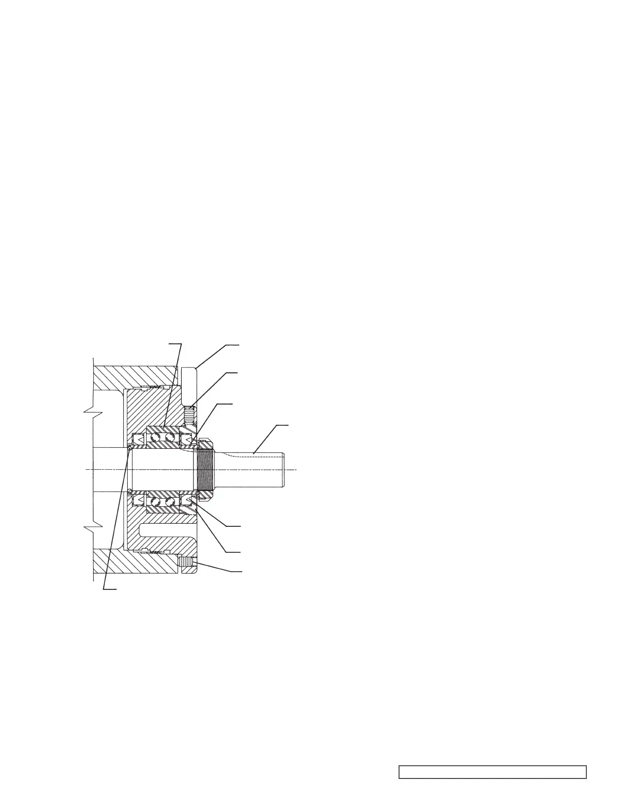
bracket. Refer to Figure 10.
FIGURE 10
HALF ROUND
RINGS
END CAP
LIP SEAL
SPACER COLLAR
SETSCREW
SHAFT
SETSCREW
BEARING HOUSING
BALL BEARING
1. Install bracket bushing. If bracket bushing has a
lubrication groove, install bushing with groove at
6 o’clock position in bracket. If carbon graphite, Refer
to Installation of Carbon Graphite Bushings, page 8.
2. Coat shaft of rotor shaft assembly with light oil. Start
end of shaft in bracket bushing turning from right to left,
slowly pushing rotor in casing.
3. Coat idler pin with light oil and place idler and bushing
on idler pin in head. If replacing with carbon graphite
bushing, Refer to installation of Carbon Graphite
Bushings, page 8.
4. Using a .010 to .015 inch head gasket, install head and
idler assembly on pump. Pump head and casing were
marked before disassembly to insure proper reassembly.
If not, be sure idler pin, which is offset in pump head,
is positioned toward the equal distance between port
connections to allow for proper flow of liquid through
pump. If pump is equipped with jacketed headplate,
install at this time along with new gasket.
Tighten head capscrews evenly.
5. When assembling packed pump, use packing suitable
for liquid being pumped. Install packing, staggering the
joints from one side of shaft to other. Lubricate packing
rings with oil, grease, or graphite to aid assembly. Install
packing gland, capscrews, and nuts. Make sure gland is
installed square and nuts are tightened evenly. Tighten
nuts until packing gland is snug against packing.
6. Slide inner spacer collar over shaft with recessed end
facing rotor. G, H and HL size bearing spacer collars are
not recessed.
Place pair of half round rings on shaft and slide inner
bearing spacer collar over half round rings to lock them
in place. There is no pair of half round rings on the G, H
and HL size pumps.
7. Install the lip seal (lip toward end of shaft) in the bearing
housing and turn the bearing housing into the bracket.
8. Pack the ball bearing with grease, place on the shaft and
push or drive into place in housing.
Note: G size has sealed bearing.
5. Remove pair of half round rings under the inner spacer
collar from the shaft. There are no half round rings on the
G, H and HL size pumps.
6. Remove packing gland capscrews, slide packing gland
out of stuffing box, and remove packing.
NOTE: Reference cartridge seal replacement beginning
on page 4 when disassembling seal pump.
7. Carefully remove rotor and shaft to avoid damaging
bracket bushing.
8. Loosen two radial setscrews in flange of bearing housing
and with a spanner wrench remove the outer end cap
with lip seal and outer bearing spacer collar.
9. Remove the double row ball bearing, lip seal and inner
bearing spacer collar from the bearing housing.
10. Clean all parts thoroughly and examine for wear and
damage. Check lip seals, ball bearing, bushings, and
idler pin and replace if necessary. Check all other parts
for nicks, burrs, excessive wear and replace if necessary.
Wash bearings in clean solvent. Blow out bearings with
compressed air. Do not allow bearings to spin; turn them
slowly by hand. Spinning bearings will damage race and
balls. Make sure bearings are clean, then lubricate with
light oil and check for roughness. Roughness can be
determined by turning outer race by hand.
Note: G size has sealed bearings.
11. Casing can be checked for wear or damage while
mounted on bracket.