6
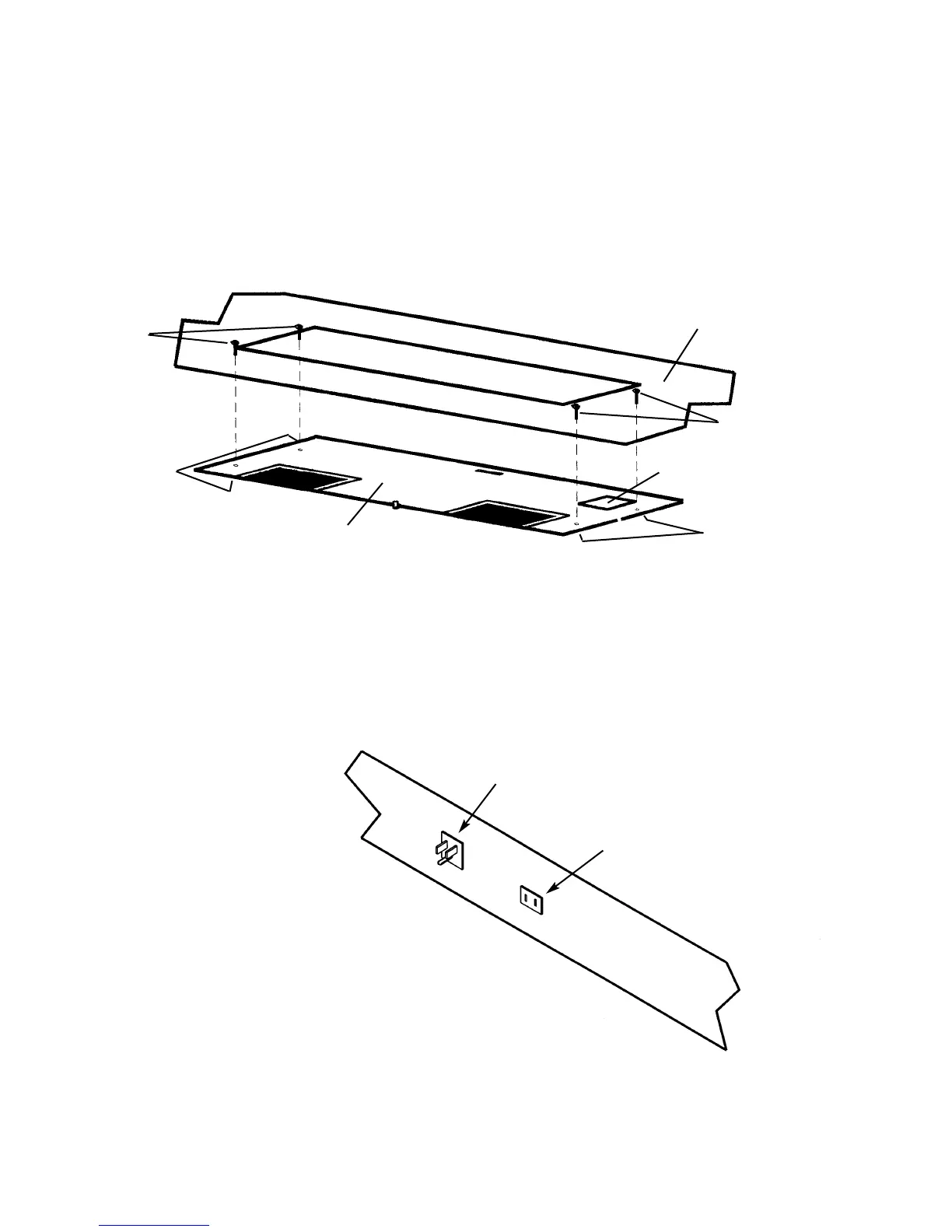
IINNSSTTAALLLLIINNGG RROOUUGGHH--IINN PPLLAATTEE AANNDD CCOONNNNEECCTTIINNGG DDUUCCTT -- IINNTTEERRNNAALL PPOOWWEERR
((AAllssoo sseeee iinnssttrruuccttiioonnss ssuupppplliieedd wwiitthh vveennttiillaattoorr kkiitt))
1. Attach rough-in plate to studs in the inside, top of hood with four (4) #10-24 nuts provided.
2. Connect ductwork using supplied transition and damper (transition and damper are part of rough-in plate on some
models). Use duct tape to make all joints secure and air tight. In some installations, it is easier to attach transition
to plate before attaching plate to hood.
3. Remove wire box cover. Remove a knockout from the wiring box. Feed 6” of power cable through opening and
attach cable to wiring in wiring box with appropriate connector.
WWAARRNNIINNGG
: MAKE SURE ELECTRICAL SUPPLY IS
OFF.
4. Wire black to black, white to white, and green or bare wire beneath green ground screw. Replace wire box cover.
5. Plug the rough-in plate power cord into the receptacle located on the top side of the light panel.
Top of Hood
Studs
Nuts
Rough-in
Plate
Wire box cover
Nuts
Studs
3-prong power
supply plug-in
2-prong blower plug-in
Receptacles are located
behind and above control
panel
 Loading...