BLADDER TANK MODEL VFT & FT
INSTALLATION, OPERATION AND
MAINTENANCE MANUAL
(
foam concentrate inside the bladder
)
TECHNICAL
MANUAL
F_032216 16.1 | TM1.3.1.1/14032016/en
The Viking Corporation, 210 N Industrial Park Drive, Hastings MI 49058
Telephone: 269-945-9501 Technical Services: 877-384-5464 Fax: 269-818-1680 Email: techsvcs@vikingcorp.com
VISIT THE VIKING WEBSITE FOR THE LATEST EDITION OF THIS TECHNICAL MANUAL
Page 22 of 35
14. Once partial lling or lling to nominal capacity is complete, a water supply hose should be connected to the water ll/drain
valve (7). Water must then be transferred into the tank, by slowly opening valve (7) and venting air through valves (2) and (5)
always ensuring the pressure is less than 1 kPa at pressure gauge (6).
Water lling must continue until water, free of air bubbles, is drained though valve (2) and until foam concentrate, after some
seconds, is drained through the valve (5).
Close the valves (7), (2) then (5). The bladder tank condition is described in gure 7.3.8;
15. Disconnect the foam pump hose from the tank and clean foam pump and hoses
16. Disassemble the lling device (6)/(5) and restore the concentrate vent valve (4) as shown in gure 3.3.1.
The lling process is now nished.
This section also applies to any foam lling after the rst one. When re-lling because the tank is empty to 75% full of foam
concentrate, please ensure that the initial relevant conditions are as those described from the beginning of paragraph 7.3. Note
that in cases where the tank is not completely emptied, the air supply described in gure 7.3.5 should be connected to the lling
device valve (5).
If the bladder tank needs to be re-lled and is more than 75% full as illustrated in gure 7.3.8, the lling activity shall follow all the
relevant steps described in this section until the end of the process. Water should be drained from the tank to allow room for new
concentrate to be poured in manually through the top bladder vent valve or pumped in through foam concentrate ll valve (8).
To check the foam level inside the bladder tank, please refer to the instruction in Section 9.
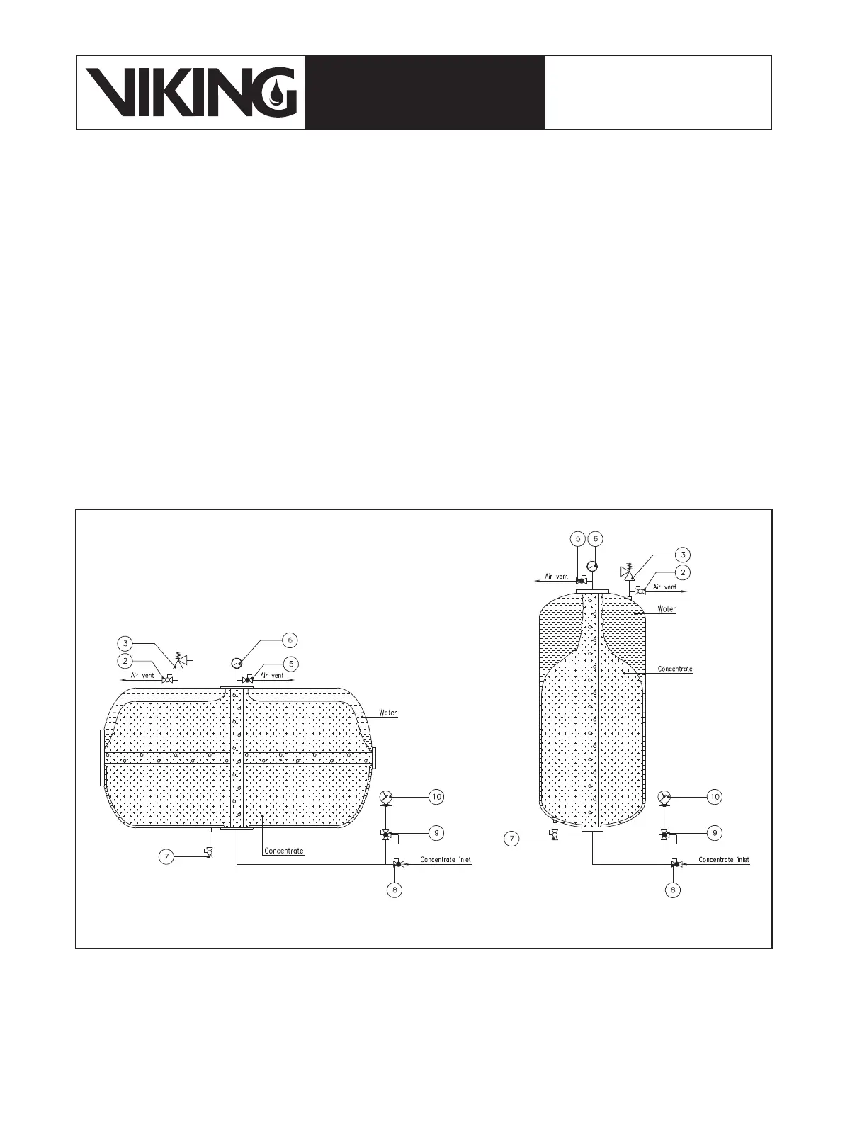
Figure 7.3.8: Bladder tank lled by foam up to partial capacity