BLADDER TANK MODEL VFT & FT
INSTALLATION, OPERATION AND
MAINTENANCE MANUAL
(
foam concentrate inside the bladder
)
TECHNICAL
MANUAL
F_032216 16.1 | TM1.3.1.1/14032016/en
The Viking Corporation, 210 N Industrial Park Drive, Hastings MI 49058
Telephone: 269-945-9501 Technical Services: 877-384-5464 Fax: 269-818-1680 Email: techsvcs@vikingcorp.com
VISIT THE VIKING WEBSITE FOR THE LATEST EDITION OF THIS TECHNICAL MANUAL
Page 29 of 35
10.4 Bladder connections - bolts tightening torque adjustment
The separation bladders used in Viking bladder tanks are made by synthetic materials whose consistency is similar to that of the
rubber. In particular, the top and bottom caps are made of synthetic rubber. These two caps provide the xing of the bladder to the
rest of the tank. They are installed in a wafer conguration between the tank ingots and the top and bottom closure anges.
Environmental changes, such as temperature and humidity, vibration and periodic uctuation of the bladder working pressure may
result in small leaks of water or concentrate if a periodic adjustment of the tightening torque at the top and bottom bladder ange
bolt’s is not made.
Leaks of foam concentrate from the top ange may damage the tank painting if not readily eliminated
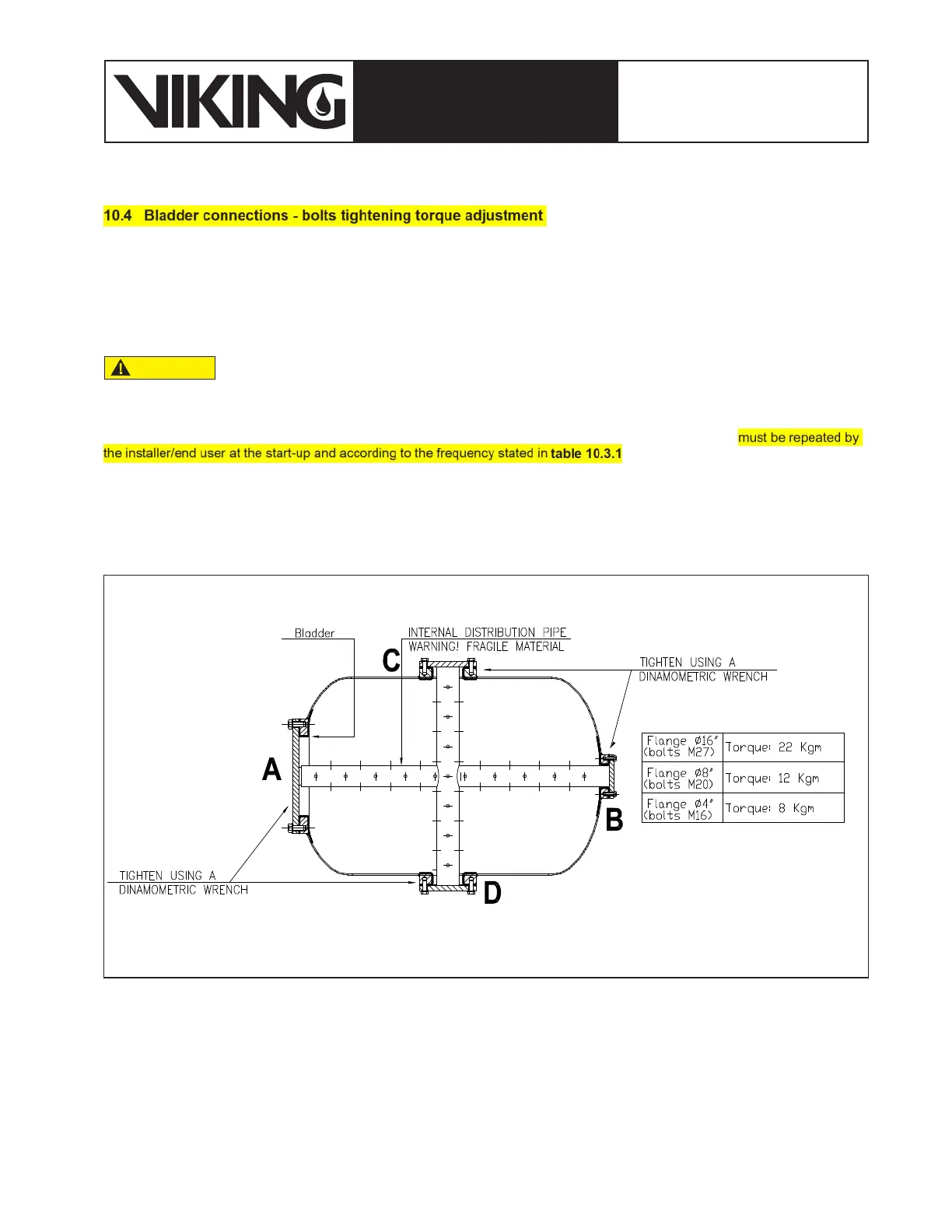
The bolt tightening operation is made for the rst time in the factory as part of the manufacturing process and must be repeated by
the installer/end user at the start-up and according to the frequency stated in table 10.3.1.
The procedure to tighten the bolts requires the use of a dynamometric (torque) wrench and is described as follows:
1. Starting from the top ange and using a dynamometric wrench, tighten each diagonally opposite bolts in sequence. Torque
value is indicated in gure 10.4.1 based on different ange/bolt sizes.
2. Perform the same activity on the bottom ange
CAUTION
Figure 10.4.1: Torque value for top and bottom anges of Horizontal and Vertical Bladder Tanks