BLADDER TANK MODEL VFT & FT
INSTALLATION, OPERATION AND
MAINTENANCE MANUAL
(
foam concentrate inside the bladder
)
TECHNICAL
MANUAL
F_032216 16.1 | TM1.3.1.1/14032016/en
The Viking Corporation, 210 N Industrial Park Drive, Hastings MI 49058
Telephone: 269-945-9501 Technical Services: 877-384-5464 Fax: 269-818-1680 Email: techsvcs@vikingcorp.com
VISIT THE VIKING WEBSITE FOR THE LATEST EDITION OF THIS TECHNICAL MANUAL
Page 17 of 35
7.3 Bladder tank rst lling
The status of the Viking bladder tank’s relevant valves before the rst lling, making reference to gure 3.3.1, must be as described
table 7.3.1. Valve 5 and Gauge 6 are part of the temporary lling device previously described.
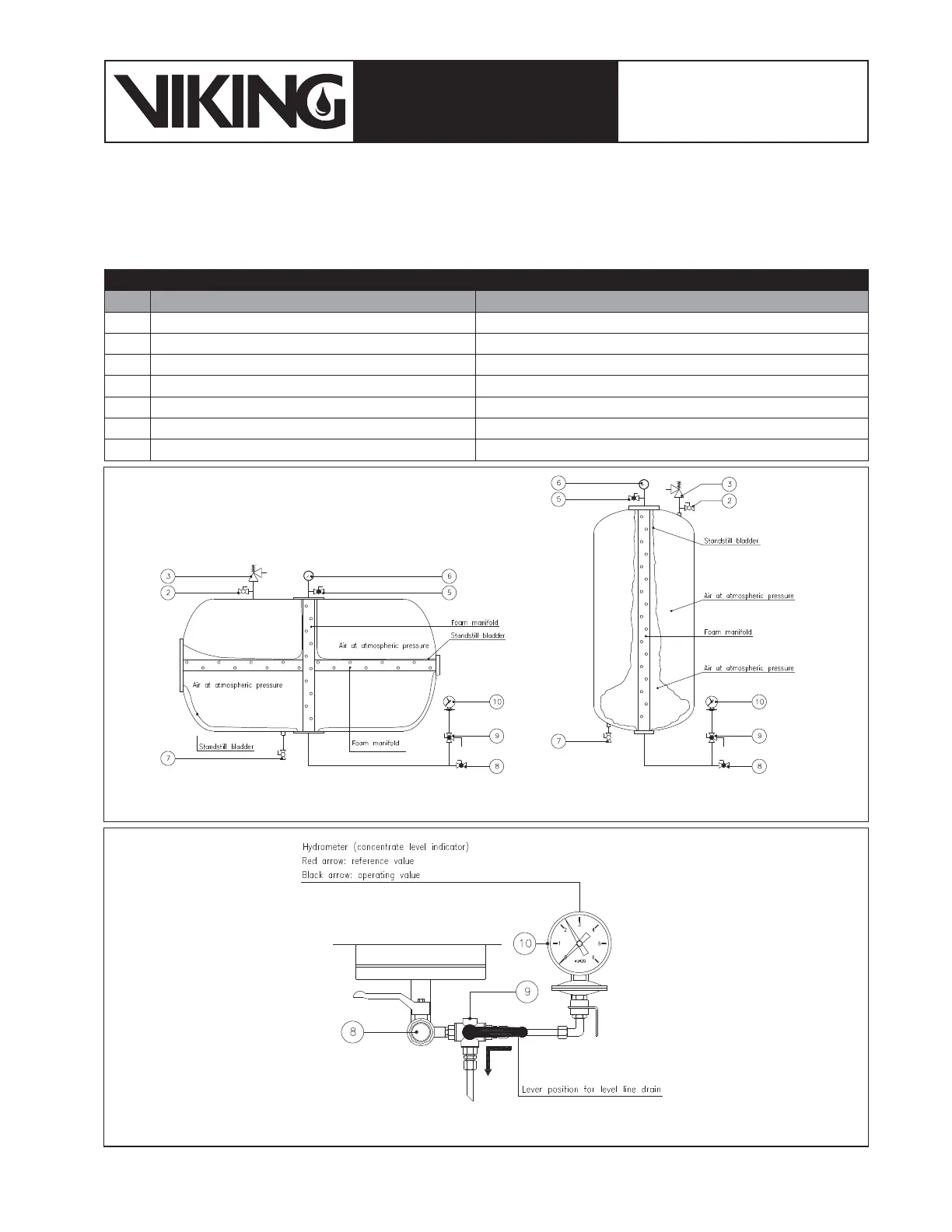
Table 7.3.1: valves condition before the bladder tank lling
Item Valve Name Status
2 Water vent valve Open
7 Water lling/drain valve Open
8 Concentrate lling/drain valve Closed
9 Concentrate level indicator drain valve Liquid Indicator Isolated from Tank (g. 7.3.3)
11 Water cut-off valve Closed
12 Concentrate cut-off valve Closed
- Concentrate Control Valve (CCV, if any) Open (priming trim depressurized)
Figure 7.3.3: Detail of the devices to be operated at the beginning of the lling
Figure 7.3.2: Detail of the devices to be operated at the beginning of the lling