BLADDER TANK MODEL VFT & FT
INSTALLATION, OPERATION AND
MAINTENANCE MANUAL
(
foam concentrate inside the bladder
)
TECHNICAL
MANUAL
F_032216 16.1 | TM1.3.1.1/14032016/en
The Viking Corporation, 210 N Industrial Park Drive, Hastings MI 49058
Telephone: 269-945-9501 Technical Services: 877-384-5464 Fax: 269-818-1680 Email: techsvcs@vikingcorp.com
VISIT THE VIKING WEBSITE FOR THE LATEST EDITION OF THIS TECHNICAL MANUAL
Page 18 of 35
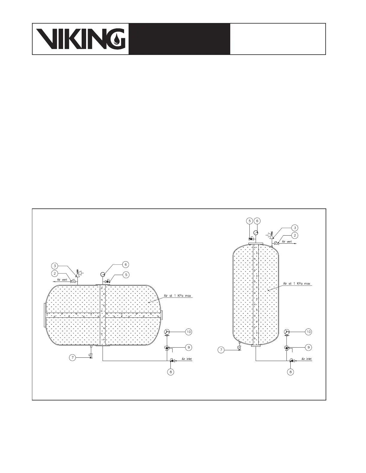
With reference to Figure 3.3.1. the bladder tank lling is made following the steps below:
1. Make sure that the three way valve (9) is set to put in communication the liquid indicator and the drain, so as to isolate the in-
strument from the bladder tank (see gure 7.3.3). (Pressure in excess of 0.6 bar applied to the level indicator may damage it).
2. Keep valves (11) and (12) closed and open the valves (2) and (7). Some water drainage from valve (7) is normal as all Viking
bladder tanks are hydrotested during the manufacturing process. The bladder tank’s condition at this stage is represented in
gure 7.3.2.
3. Remove the foam vent valve (4) and assemble the lling device in place of it (gure 3.3.1).
4. The air vent valve on the lling device (5) must be closed;
5. Connect a compressed air source having the features described in 7.2(e) to the foam ll/drain valve (8) (The Viking bladder
tank standard connection is 25mm BSP female thread).
6. Close the water drain valve (7) and open the foam lling/drain valve (8).
7. Start the air compressor or open the installation’s air network valve to inate the bladder taking care to operate these devices
and/or the foam lling/drain valve (8) to achieve a maximum air pressure of 1 kPa as shown by the lling device pressure
gauge (6).
8. Once the bladder is pressurized at 1 kPa pressure, close the concentrate lling/drain valve (8) to stop the air ow. Turn off the
air compressor or disconnect the air network. The bladder tank condition after this operation is described in gure 7.3.4;
Figure 7.3.4: Bladder tank after the bladder air lling at 1 kPa