BLADDER TANK MODEL VFT & FT
INSTALLATION, OPERATION AND
MAINTENANCE MANUAL
(
foam concentrate inside the bladder
)
TECHNICAL
MANUAL
F_032216 16.1 | TM1.3.1.1/14032016/en
The Viking Corporation, 210 N Industrial Park Drive, Hastings MI 49058
Telephone: 269-945-9501 Technical Services: 877-384-5464 Fax: 269-818-1680 Email: techsvcs@vikingcorp.com
VISIT THE VIKING WEBSITE FOR THE LATEST EDITION OF THIS TECHNICAL MANUAL
Page 19 of 35
9. Water shall be added outside the bladder in order to prepare it for foam lling. To do that, connect a water hose (for example
from a hydrant or hose connection) to the water drain valve (7).
The water drain valve standard connection is 25mm BSP female thread. Pressurize the hose line and open
partially and slowly the water drain valve (7), whilst operating the air vent valve (5) in such a way that the incoming water
volume equals exactly the vented air and the bladder air pressure remains, steadily, at 1 kPa.
Stop the water lling by closing the valve (7) when approximately 10% of the bladder tank nominal capacity has been lled with
water. Close the valve (5) if it has been previously opened.
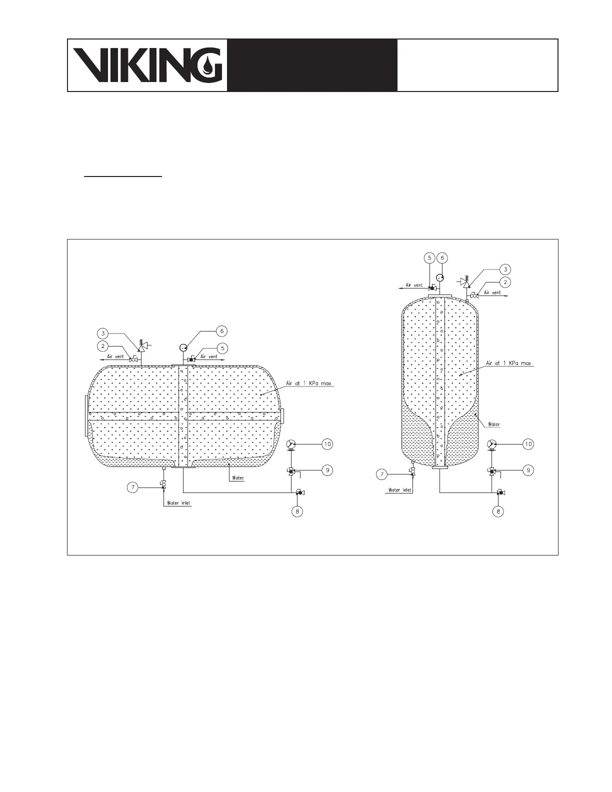
The condition of the bladder tank after this operation is described in gure 7.3.5;
10. Disconnect the water hose from valve (7) and connect the delivery hose of the foam lling pump, having the features described
in 7.1(d), to the foam lling/drain valve (8);
11. Place the foam lling pump suction tube inside the foam concentrate container.
Figure 7.3.5: Bladder tank after the external water lling