BLADDER TANK MODEL VFT & FT
INSTALLATION, OPERATION AND
MAINTENANCE MANUAL
(
foam concentrate inside the bladder
)
TECHNICAL
MANUAL
F_032216 16.1 | TM1.3.1.1/14032016/en
The Viking Corporation, 210 N Industrial Park Drive, Hastings MI 49058
Telephone: 269-945-9501 Technical Services: 877-384-5464 Fax: 269-818-1680 Email: techsvcs@vikingcorp.com
VISIT THE VIKING WEBSITE FOR THE LATEST EDITION OF THIS TECHNICAL MANUAL
Page 20 of 35
12. Open the foam lling/drain valve (8) and activate the foam pump to ll the bladder.
During this operation open partially the vent valve (5) to equalize the incoming foam volume with the vented air from the
bladder, in such a way to maintain constantly a maximum pressure of 1 kPa as indicated by the pressure gauge (6).
The bladder tank condition evolves as indicated in gure 7.3.6
13. Keep pumping the foam into the bladder tank, always making sure that the maximum pressure of 1 kPa is not exceeded. In
case the bladder tank is to be lled to its total nominal capacity or less than its total nominal capacity (partial lling), pumping of
foam must continue until the available foam reservoir is emptied.
Viking bladder tanks have a real capacity higher than the nominal to allow for foam concentrate thermal expansion under the
worst expected temperature conditions within the design limits. As a consequence, water is normally vented through valve (2)
in case of lling to nominal capacity or less while the foam amount is not enough to be make it discharged through (5). A water
cushion remains outside the bladder. At this stage the pump can be stopped and the valves (5) and (8) can be closed
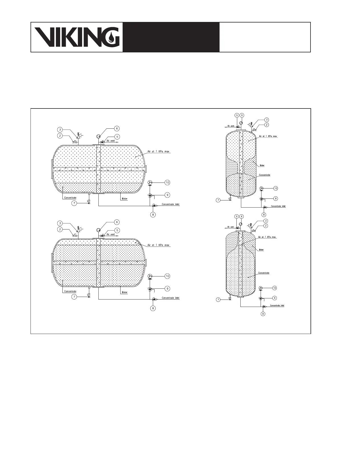
Figure 7.3.6: Bladder tank foam lling evolution (from top to bottom)