BLADDER TANK MODEL VFT & FT
INSTALLATION, OPERATION AND
MAINTENANCE MANUAL
(
foam concentrate inside the bladder
)
TECHNICAL
MANUAL
F_032216 16.1 | TM1.3.1.1/14032016/en
The Viking Corporation, 210 N Industrial Park Drive, Hastings MI 49058
Telephone: 269-945-9501 Technical Services: 877-384-5464 Fax: 269-818-1680 Email: techsvcs@vikingcorp.com
VISIT THE VIKING WEBSITE FOR THE LATEST EDITION OF THIS TECHNICAL MANUAL
Page 9 of 35
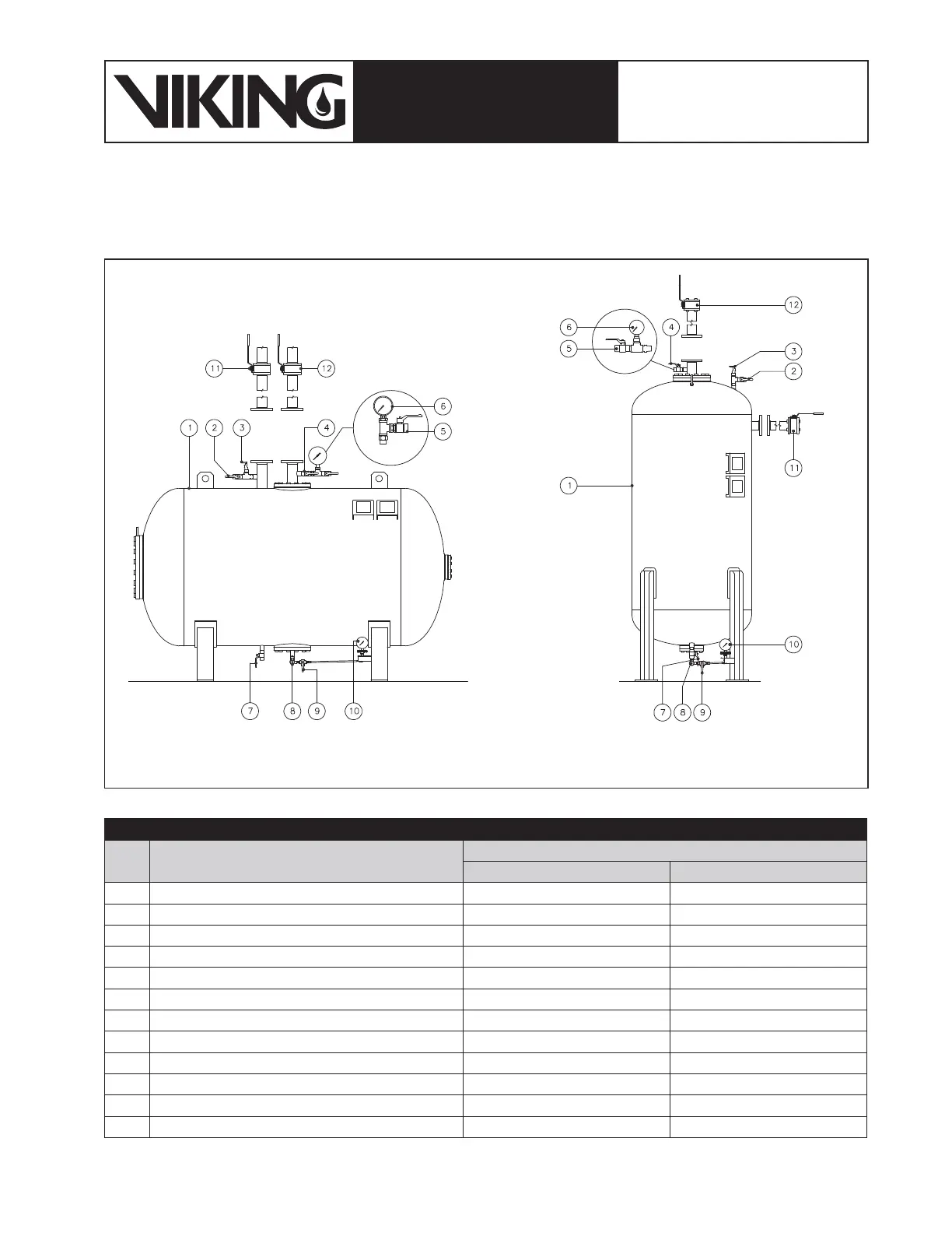
3.3 Bladder tank layout
The layout and the position of the accessories of the bladder tank are shown in gure 3.3.1.
Filling Device
(Optional)
Filling Device
(Optional)
Table 3.3.2: Normal Operating Valve Positions
Item Description
Normal Valve Operating Position
Automatic System Manual System
1 Bladder Tank N/A N/A
2 Water Vent Valve Normally Closed Normally Closed
3 Safety Thermal Relief Valve Automatic – Tamper Proof Automatic – Tamper Proof
4 Foam Concentrate Vent Valve Normally Closed Normally Closed
5 Filling Vent Valve (Optional) Maintenance Only Maintenance Only
6 Filling Pressure Gauge 1-10 kpa (Optional) Maintenance Only Maintenance Only
7 Water Filling/Drain Valve Normally Closed Normally Closed
8 Foam Concentrate Filling/Drain Valve Normally Closed Normally Closed
9 Concentrate Level Indicator Drain Valve Normally Closed Normally Closed
10 Concentrate Level Indicator Normally Closed Normally Closed
11 Water Shut Off Valve Normally Open Normally Closed
12 Foam Concentrate Shut Off Valve Normally Open Normally Closed
Figure 3.3.1: bladder tank arrangement