Do you have a question about the Viking VGSC530 and is the answer not in the manual?
Provides key safety messages, explains warning symbols (DANGER, WARNING, CAUTION), and lists emergency gas procedures.
Details product warranties, including duration and coverage, and outlines procedures for obtaining warranty service.
Explains how to locate and interpret serial/model numbers and provides detailed appliance dimensions.
Lists technical specifications for the ranges and specifies minimum clearances for safe installation.
Covers crucial operational warnings, fire prevention, and procedures to follow in case of a fire.
Provides guidelines for safe cleaning and cautions against improper usage, such as using as a heater.
Details electrical and gas requirements, including connection procedures and safety warnings.
Outlines pre-operation checks for proper function and initial preparation steps for the oven.
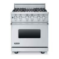
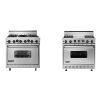
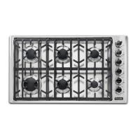
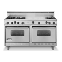
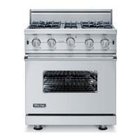
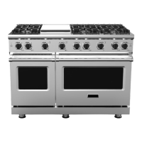
Identifies and illustrates the main features, controls, and components of the Viking range.
Explains LED error codes for ovens/griddles and shows thermostat control wiring diagrams.
Lists DSI board fault codes and illustrates Direct Spark Module wiring connections.
Details RH oven LED error codes and shows self-cleaning oven control board connections.
Provides a troubleshooting guide for RH oven components, listing symptoms, causes, and corrections.
Offers troubleshooting steps for LH oven components, covering inoperable functions and potential causes.
Addresses troubleshooting for surface burner igniters, flame issues, and griddle malfunctions.
Step-by-step guide to diagnose RH oven bake operation issues by checking electrical components.
Diagnostic flowchart for troubleshooting oven broil operation, including electrical and gas checks.
Guides troubleshooting for the 48" LH oven, checking thermostat, DSI module, and solenoid.
Outlines diagnostic steps for griddle operation, focusing on electrical and gas component checks.
Presents tables of resistance values for selector and thermostat positions for diagnostic purposes.
Details operating voltage, resistance, and test locations for various range components.
Provides procedures for testing the spark module and explains RTD temperature characteristics.
Step-by-step instructions for removing the oven door assembly and its gasket.
Guides on removing the door handle, logo, and hinges from the oven door assembly.
Instructions for carefully removing the outer and inner door glass panels.
Details the process for removing the bake burner igniter and the bake burner itself.
Provides steps for removing the bake burner orifice and the convection fan assembly.
Instructions for accessing and removing the control panel assembly and its components.
Guides on removing oven controls, thermostats, selectors, and the door latch assembly.
Instructions for removing the control board, direct spark module, high limit, and door switches.
Procedures for replacing oven light bulbs, side housing, switch, and indicator lights.
Steps to remove burner orifices, burner base assembly, and surface burner valves.
Guides on removing shutoff valves, IRIS modules, and char-grill burners and igniters.
Instructions for removing griddle sensor, burner, igniter, island trim, and backguard.
Steps to remove the main top assembly and the jet holder.
Procedures for removing the cooling fan assembly for various Viking range models.
Instructions for removing the gas solenoid valve and pressure regulator.
Guides on removing side trims, side panels, kick plates, and hinge receivers.
Steps for removing the back panel and the RTD sensor for the VGSC548 left oven.
Procedures for removing RTD sensors for the right oven (VGSC530/548) and VGSC536 oven.
Instructions for removing gas tubing connected to the bake and broil burners.
Detailed steps for removing the broil burner, including igniter and bracket components.
Wiring diagrams for griddle control systems (VGSC536) and oven/griddle systems (VGSC548).
Wiring diagram for the oven control thermostat and DSI module system on VGSC548-8B/6Q models.
Comprehensive wiring diagram for the VGSC530 gas self-clean range.
Detailed wiring diagram for the VGSC536-4G gas self-clean range.
Wiring diagram for the VGSC536-6B/4Q gas self-clean range.
Wiring diagram for the VGSC548-4GQ/6G gas self-clean range.
Wiring diagram for the VGSC548-6Q/8B gas self-clean range.
| Type | Freestanding |
|---|---|
| Width | 30 inches |
| Burners | 4 |
| Oven Type | Convection |
| Ignition System | Electronic |
| Finish | Stainless Steel |
| Oven Capacity | 4.0 cu ft |
| BTU Output | 15, 000 BTU |
| Dimensions | 30" W |