Component Testing Procedures
© Viking Range Corporation SMC-0002 13
To avoid risk of electrical shock, personal injury, or death; disconnect power and shut off gas to unit before
servicing, unless testing requires power.
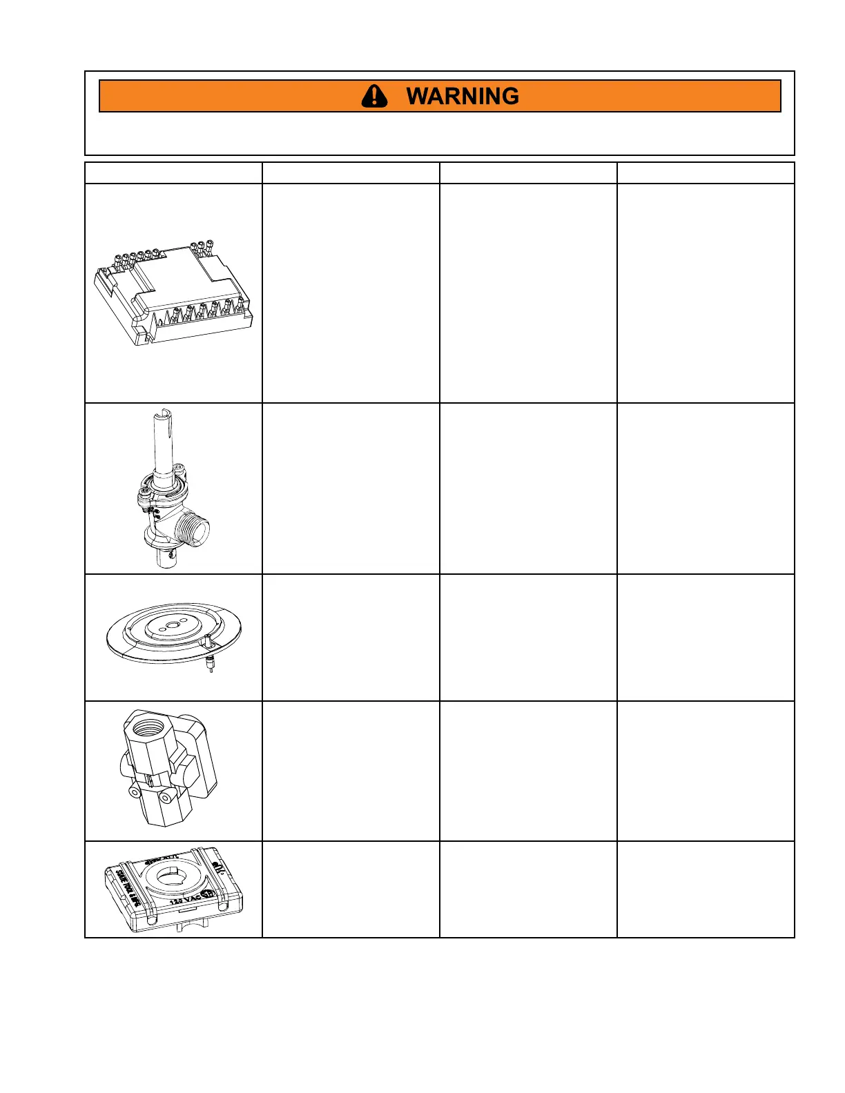
Illustration Component Test Procedure Results
Spark module Test for voltage at Line
and Neutral........................
Polarity...............................
120 VAC •
If the Line and Neutral •
connections to the
igniter are reversed, the
sensitivity is reduced;
and the unit may not
sense a ame. As a
result, sparking may
occur when a ame is
present.
Gas Valve Verify gas is supplied
Adjust set screw for low
ame
Sealed Burner Base Verify gas is supplied.........
Verify igniter function..........
Verify burner cap is
positioned correctly
Check for obstructions •
in burner ports
Test continuity across •
spark lead and
igniter. Ensure innite
resistance from igniter
to burner base.
Pressure Regulator Verify gas pressure............
If on LP service, verify
proper gas supply
conversion
Verify proper conversion (if
on LP)
5" WCP for natural •
10" WCP for LP
Micro Switch Harness
Test for continuity in all
positions............................. Switch should read •
continuity in all
positions except for
OFF (innite resistance)


 To Next Page