Do you have a question about the Viking VICU206 and is the answer not in the manual?
Provides critical safety messages and explains safety alert symbols like DANGER, WARNING, and CAUTION.
Details the twelve-month warranty for materials and workmanship for normal household use.
Covers electric elements failing due to defects in the second through fifth year, covering parts but not labor.
Applies to non-commercial use extending beyond typical residential, excluding commercial locations.
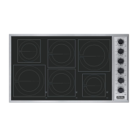
Provides technical specifications for VICU206 and VICU266 Induction Cooktops, including dimensions and electrical requirements.
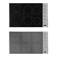
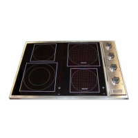
Details technical specifications for VCCU106 and VCCU166 Induction/Radiant Ceramic Cooktops, including dimensions and electrical ratings.
Details crucial safety warnings regarding electrical grounding, extension cords, and burn hazards.
Explains cookware compatibility for induction cooktops, including suitable materials and recommended dimensions.
Explains how to interpret model numbers and locate serial numbers on the data plate for identification.
Describes the function and location of surface indicator lights used for activation, hot surface, and warnings.
Provides detailed instructions for cleaning the glass ceramic top, control panel, knobs, and stainless steel parts.
Explains how the thermostat digital display alerts users to errors and lists LED codes with their possible reasons and actions.
Continues the list of built-in error codes, detailing failures, possible reasons, and recommended corrective actions.
Explains the fundamental principles of induction cooking, how it differs from other methods, and how heat is generated.
Illustrates the process of induction cooking, showing magnetic fields, induced currents, and heat transfer to the cooking vessel.
Details built-in safety features of induction cooking, including pot detection, cool surface temperatures, and overheat protection.
Provides an overview of component serviceability and accessibility, indicating which parts are front serviceable or require partial/full removal.
Illustrates the physical layout and identifies key components within the cooktop.
Provides step-by-step instructions for disassembling the all-induction cooktop.
Continues the disassembly process for the all-induction cooktop, focusing on internal components.
Details the initial steps for disassembling the induction/radiant cooktop, including knob removal and ceramic top detachment.
Continues the induction/radiant cooktop disassembly, covering inductor disconnections and removal of front/rear inductors.
Further disassembly steps for induction/radiant cooktops, focusing on removing upper filter/power board covers and modules.
Completes the induction/radiant cooktop disassembly by removing lower filter/power board covers and modules.
Provides a table detailing voltage, resistance, and amp specifications for various components, along with test locations.
Offers a guide to common problems, their probable causes, and recommended corrections for cooktop malfunctions.
Explains the function of the induction switch, how to access it, and provides resistance charts for testing.
Details the function of infinite switches for radiant burners, how to access them, and verification procedures.
Describes the inductor's role in induction cooking, its connection to the power board, and troubleshooting steps.
Explains the function of the indicator light in detecting pots and errors, and provides steps for checking its connection and replacement.
Details the interface board's function, its connections, and important notes regarding replacement and potential errors.
Explains the power board's role in energizing the inductor and provides troubleshooting steps for its connection and power output.
Describes the filter board's function, its connections to the power board and interface, and troubleshooting steps including fuse checks.
Details the cooling fan's role in heat management and lists its electrical specifications.
Explains the NTC sensor's function in protecting inductors and detecting overheat situations, with a resistance chart for testing.
Presents the wiring diagram for the 30-inch wide VCCU model, illustrating component connections and signal paths.
Provides the wiring diagram for the 36-inch wide VCCU model, showing all electrical connections and component layouts.
Illustrates the wiring diagram for the 30-inch wide VICU model, detailing the connections between control switches, interfaces, and indicator boards.
Presents the wiring diagram for the 36-inch wide VICU model, mapping connections for control switches, interfaces, and indicator boards.
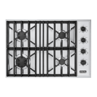
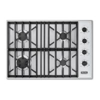
| Number of Burners | 4 |
|---|---|
| Dimensions | 20 5/8" W x 20 1/2" D |
| Weight | 30 lbs |
| Type | Gas |
| Control Type | Knob |
| Gas Type | Natural Gas / LPG |