© 2009 Viking Preferred Service
29
Service Diagnostics and Procedures
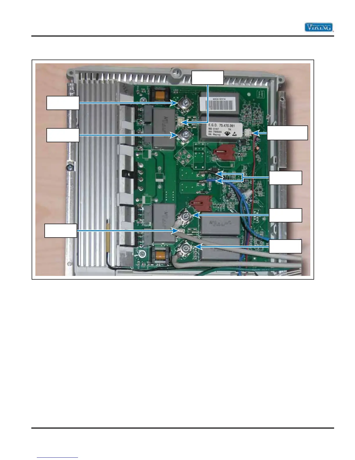
Power Board
The power board is part of the generator used
to power the inductor. Once a selection is made
by the end user, the interface communicates with
the filter board, which in turn sends power to the
power board. Once the power board is energized,
the inductor is energized and induces energy into
the cooking vessel generating heat. Wattage per
cooking zone 3200W max. Total wattage X6 to X9
3700W
The power board is connected to the filter board
via a cable. Ensure connection to the filter board
cable X10 (power board) – X58 (filter board), blue
wire via X55, and black wire via X56. X4 and X5 are
connection points for the sensor wires, X6/ X7, X8/
X9 are terminals for the inductor leads.
If wiring is proper, connections are tight, 240 VAC
Blue to Black is present at the inductor replace the
power board. If no power at the inductor and the
filter board has 240 VAC L1 (X50) to L2 (X52), the
20 amp fuse (E23 – E22) at the filter board is not
open, and voltage is found at blue and black wires
at power board, replace the power board. If no
voltage at blue and black wires at power board and
connections are proper, replace filter board.
From RF, LF
Inductor
From RR, LR
Inductor
Communication
from Filter Board
Power out to
LF, RF
Power out to
LR, RR
Power out to
LF, RF
Power out to
LR, RR
Power in from
filter board