Viale Vicenza, 14
36063 Marostica VI - Italy
www.vimar.com
49401399B0 00 2006
7549
• Vista retro
• Rear view
• Face arrière
• Rückansicht
• Vista posterior
• Vista traseira
• Πίσω πλευρά
•
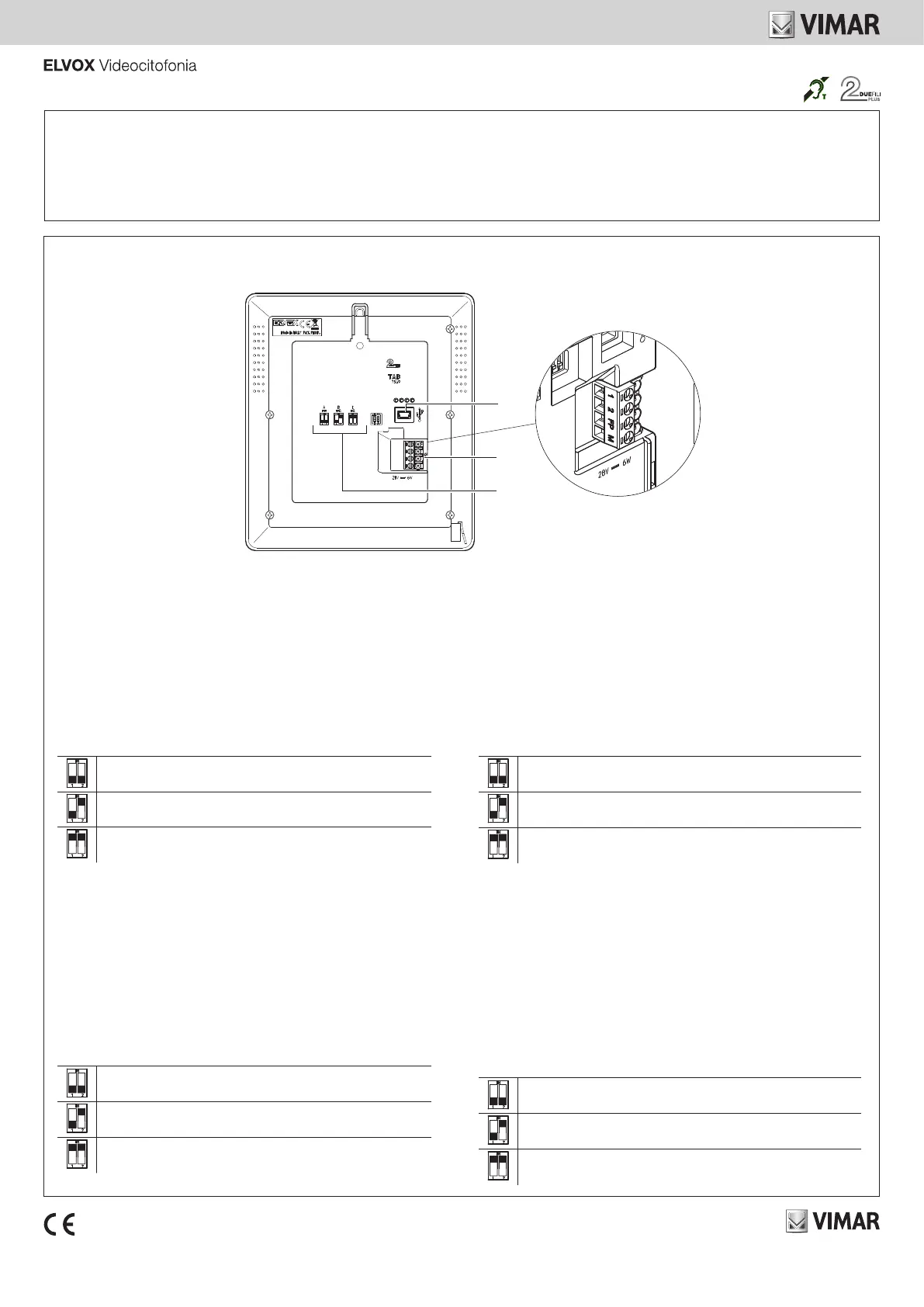
1 - USB connector for programming using software
2 - Connection terminal block
1, 2 = Digital BUS line
FP * = Local Landing Call (reference to terminal M).
When congured using SaveProg, this input can be used for the “Alert”
function. See the relevant paragraph in the use and installation manual.
Note: the FP/M pair of terminals can also be used, when use as “Alert” is not
active, to simulate a call from Art. 6120 intended for the master with respect
to any of its secondary indoor stations.
M * = Earth
3 - Conguration dip switch (Bus termination)
Note: * the maximum connection distance to the terminals is 10 m.
SWITCH TABLE
A = the BUS cable enters terminals 1, 2 and continues to another indoor
station
B = The BUS cable with a characteristic impedance of 100 Ohms (Elvox
732I or 732H cable) enters terminals 1, 2 and the riser stops in the indoor
station.
C = The BUS cable with characteristic impedance of 50 Ohms (Cat. 5 or
Cat. 6 twisted pair cable) enters terminals 1, 2 and the riser stops in the
indoor station.
1 - Connettore USB per programmazione da software
2 - Morsettiera di collegamento
1, 2 = Linea digitale BUS
FP * = Chiamata Fuori Porta locale (riferimento al morsetto M)
Tramite congurazione eseguita da SaveProg, può essere utilizzato come
ingresso per la funzione "Allerta". Vedere il relativo paragrafo nel manuale di
installazione e utilizzo.
Nota: la coppia di morsetti FP/M può anche essere usata, quando non è attivo
l'uso come "Allerta", per simulare nei confronti degli eventuali suoi posti
interni secondari, una chiamata da Art. 6120 diretta al capogruppo.
M * = Massa
3 - Dip Switch di congurazione "Terminazione Bus"
Nota: * la distanza massima dei collegamenti ai morsetti è di 10 m.
TABELLA SWITCH
A = Il cavo del BUS entra nei morsetti 1, 2 e prosegue ad un altro posto
interno
B = Il cavo BUS con impedenza caratteristica di 100 Ohm (cavo Elvox 732I
o 732H) entra nei morsetti 1, 2 ed il montante si ferma nel posto interno
C = Il cavo BUS con impedenza caratteristica di 50 Ohm (cavo Cat.5 o
Cat.6 con i doppini accoppiati) entra nei morsetti 1, 2 ed il montante si
ferma nel posto interno
1 - Connecteur USB pour la programmation à partir du logiciel
2 - Bornier de connexion
1, 2 = Ligne numérique BUS
FP * = Appel palier (référence à la borne M).
Après avoir procédé à sa conguration via SaveProg, il est possible de
l'utiliser comme entrée pour la fonction « Alerte ». Consulter le paragraphe
correspondant dans le manuel d'installation et d'utilisation.
Remarque : les deux bornes FP/M peuvent également être utilisées, lorsque la
fonction « Alerte » n'est pas activée, pour simuler un appel provenant de l’Art.
6120 et destiné au poste principal par rapport aux éventuels postes intérieurs
secondaires.
M * = Masse
3 - Dip-Switch de conguration (Terminaison Bus)
Remarque : * la distance maximale des connexions aux bornes correspond à 10 m.
TABLEAU SWITCH
A = Le câble du BUS arrive aux bornes 1, 2 et continue vers un autre poste
intérieur
B = Le câble BUS avec une impédance caractéristique de 100 ohms (câble
Elvox 732I ou 732H) arrive aux bornes 1, 2 et la colonne montante s'arrête
au poste intérieur
C = Le câble BUS ayant une impédance caractéristique de 50 ohms (câble
cat. 5 ou cat. 6 à paires torsadées) arrive aux bornes 1, 2 et la colonne
montante s'arrête au poste intérieur
1 - USB-Anschluss für Programmierung über die Software SaveProg
2 - Anschlussklemmenleiste
1, 2 = Digitale Busleitung
FP * = Lokaler Etagenruf (Signal an Klemme M)
Kann mittels Konguration über SaveProg als Eingang für die Funktion
"Warnmeldung" verwendet werden. Siehe entsprechenden Abschnitt in der
Installations- und Bedienungsanleitung.
Hinweis: Das Klemmenpaar FP/M kann bei nicht aktivierter Funktion
"Warnmeldung" auch dazu verwendet werden, einen von Art. 6120 an das
Gruppen-Hauptgerät gerichteten Ruf gegenüber seinen etwaigen sekundären
Innenstellen zu simulieren.
M * = Masse
3 - Dip-Schalter für Konguration (Bus-Abschluss)
Hinweis: * die maximale Anschlusslänge an die Klemmen beträgt 10 m.
SCHALTERTABELLE
A = Das BUS-Kabel tritt in die Klemmen 1, 2 ein und führt und zu einer
anderen Innenstelle weiter
B = Das BUS-Kabel mit typischer Impedanz 100 Ohm (Elvox Kabel 732I
oder 732H) tritt in die Klemmen 1, 2 ein und die Steigleitung endet an der
Innenstelle
C = Das BUS-Kabel mit typischer Impedanz 50 Ohm (Kabel Cat.5 oder
Cat.6 mit gepaarten Doppeladern) tritt in die Klemmen 1, 2 ein und die
Steigleitung endet an der Innenstelle
2
1
3
• Nota: la durata del ciclo di suoneria dipende dal tempo di pressione del tasto per un tempo massimo di 10s.
• Note: the duration of the ringtone cycle depends on how long the button is pressed, for a maximum time of 10s.
• Remarque : la durée du cycle de sonnerie dépend du temps pendant lequel on appuie sur la touche, avec un maximum de 10 secondes.
• Hinweis: Die Dauer des Ruftonzyklus hängt von der Dauer des Tastendrucks ab und beträgt maximal 10s.
• Nota: la duración del ciclo del timbre depende del tiempo que se pulse la tecla, hasta un máximo de 10 segundos.
• Nota: a duração do ciclo de campainha depende do tempo que se demora a premir a tecla por um tempo máximo de 10s.
• Σημείωση: η διάρκεια του κύκλου κουδουνιού εξαρτάται από τη διάρκεια πατήματος του πλήκτρου, η οποία μπορεί να είναι έως 10 δευτερόλεπτα.
•. 10 :

 Loading...