31
Gasifying boilers VIGAS
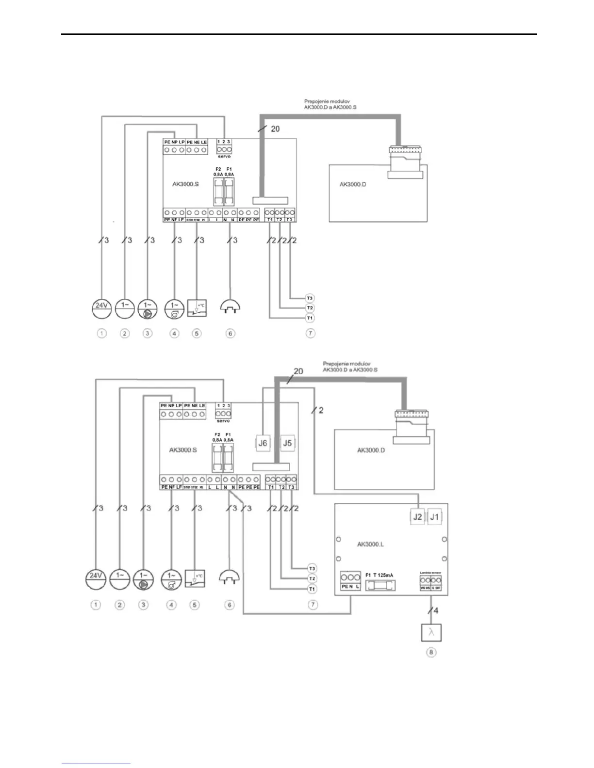
19. ELECTRIC SCHEME OF CONNECTION VIGAS BOILERS
Flow diagram of basic connection VIGAS AK 3000 boiler
Flow diagram of basic connection VIGAS
Lambda Control
AK 3000.1 boiler
1. Servosystem air control, power supply 24 VDC / 0,5A
2. Discharge fan, power supply 230 VAC / 0,6A
3. Circulation pump, power supply 230 VAC / 0,5A
4. Fab, power supply 230 VAC / 0,3A
5. Emergency thermostat STB 100
o
C
6. Power supply 230 VAC, 50 Hz
7. T1 Thermometer KTY, T2 Thermometer PT1000, T3 Indoor thermostat, no voltage, for hydraulic
scheme 2,3,4. For hydraulic scheme 1 thermometer PT 1000.
8. Lambda sensor
WS – white
WS – white
G - grey
SW - black