Do you have a question about the Vingtor Stentofon TCIS-2 and is the answer not in the manual?
Overview of the manual's content and general functions.
Overview of the manual's content and general functions.
History of document revisions, including dates, authors, and status changes.
List of supporting documents for mounting, connections, and general manuals.
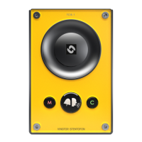
Introduction and overview of the Turbine Compact Intercom series.
Details the TKIS-2 model, including its module and connections.
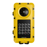
Describes Industrial and Ex variants of Turbine Extended Intercoms.
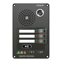
Details the ECPIR-3P indoor intercom model and its keys.
Describes the TKIE-2 model, a kit version of the Turbine Extended range.
Explains connectors for Turbine Compact stations, including power, network, and I/O.
Details connectors for Turbine Extended stations, including power, network, and I/O.
Describes connectors for Turbine Ex stations.
Instructions for connecting accessories like headsets and microphones to extended stations.
Details the TA-23/TAX-3 handset and its connection for extended intercoms.
Explains the EBMDR-8 expansion module and its connection to ECPIR-3P.
Describes the TA-10 relay module and its connections.
Steps to access the station's web interface for configuration.
Configuring station mode, IP parameters, and model selection.
Configuring audio parameters like volume, sensitivity, and voice engine.
Configuring Input/Output pins for various functions and LED patterns.
Managing station directory entries, display text, and sorting options.
Configuring display text, font size, and brightness for OLED screens.
Setting parameters for audio detection, including amplitude and duration.
Configuring network time protocol, region, and time zone.
Steps to access the IC-EDGE system's web interface.
Configuring the IC-EDGE controller and station mode.
Connecting and adding other IP intercom stations to the network.
Setting up station numbers, names, and IP addresses in the directory.
Checking the registration status of devices in the IC-EDGE system.
Setting up call and audio parameters like auto-answer and volume.
Defining service features and parameters for groups of devices.
Configuring and using the Group Call feature for multi-station communication.
Setting up the mobile application for intercom functionality.
Creating and managing a global list of registered devices and groups for the mobile app.
Configuring action buttons for call transfer, relay operation, and DTMF on the mobile app.
Registering third-party SIP devices like phones and speakers to the IC-EDGE system.
Entering advanced mode for detailed configuration of keys, scripts, etc.
Configuring call forwarding for unattended calls.
Setting up unattended call forwarding with a loopback sequence.
Configuring parallel ringing and forwarding for unattended calls.
Uploading script files for station event activation.
Configuring script slots, labels, and execution parameters.
Defining events that trigger script execution and output actions.
Uploading prerecorded audio files for playback.
Configuring audio playback triggered by DTMF tones during calls.
Setting audio playback for various call states like ringing or connection.
Configuring audio playback triggered by relay or output state changes.
Specifying audio output for messages, either speaker or speaker & mic.
Steps to access the SIP station's web interface for configuration.
Configuring station mode, IP parameters, and model for SIP stations.
Configuring SIP account details, registration, and call parameters.
Adjusting speaker volume, AGC, AVC, and ANC for SIP stations.
Configuring Direct Access Keys and Ringlist functions for SIP stations.
Configuring relay operations based on DTMF signals or station states.
Configuring network time synchronization for SIP stations.
Uploading and configuring prerecorded audio messages for SIP stations.
Enabling advanced mode for detailed SIP configuration options.
Configuring I/O pins, key matrix, and LED blink patterns for SIP stations.
Configuring SNMP for network management, traps, and informs.
Configuring 802.1X for network access authentication.
Enabling or disabling network services through the firewall.
Requirements for software upgrades, including TFTP server and image files.
Procedures for upgrading station software using the web interface.
Description of front plate LEDs for compact and industrial/ex stations.
Details of status LEDs located on the Printed Circuit Board.
Explanation of green and yellow LEDs indicating Ethernet connection status.
Procedure to reset the station to factory defaults using DHCP.
Procedure to reset the station to factory defaults using a static IP address.
Diagram and description of connectors on the front of the compact PCB.
Details of the 10-pin input connector on the compact board.
Description of output connectors and the single relay on the compact board.
Connectors for MRBD relay board, providing additional relay contacts.
Description of connectors on the rear of the compact PCB, including RS232 and microphone interfaces.
Overview of connectors and components on the front of the front board.
Overview of LEDs and keys on the rear of the front board.
Diagram and description of connectors on the front of the extended PCB.
Details of the 10-pin input connector on the extended board.
| Brand | Vingtor Stentofon |
|---|---|
| Model | TCIS-2 |
| Category | Intercom System |
| Language | English |